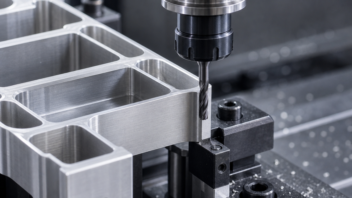
This is a hypothetical drawing-based tooling guide, not a claim about a customer project.
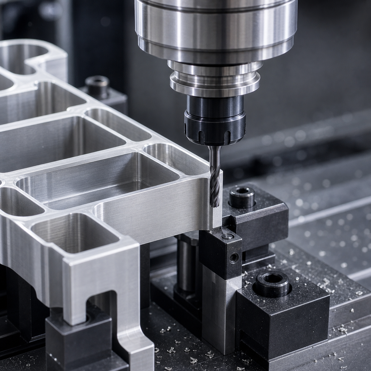
English: Thin-Wall CNC Milling Burr Control: Tool Selection, Support and Finishing Sequence
Thin-wall burr control is a stiffness and cutting-direction problem before it is a deburring problem. Read the drawing for wall thickness, free-edge length, corner radius, supported root, breakout direction and allowed edge break. A hypothetical 6061 frame uses 0.8 mm walls, R1.5 corners and a 0.10–0.20 mm edge break; the final wall pass must direct force into support, not into the released lip.
Turn the drawing into a support map
Mark every edge as supported, partially supported or free at each operation. Keep sacrificial ribs or tabs beside long walls during pocket roughing and remove them only after the root and wall thickness are stable. A vacuum plate supports broad sheet but does not stop a tall wall from breathing, so local backing or staged depth remains necessary.
Select separate roughing and finishing edges
Rough with a 10 mm three-flute polished carbide radius end mill for aluminum, high-helix positive geometry, uncoated or ZrN/DLC where adhesion warrants it, held in a low-runout shrink-fit or precision collet. Semi-finish with a 6 mm three-flute relieved-neck tool. Finish with a dedicated sharp 4–6 mm tool at minimum reach. Reject a worn rougher for the last pass because its edge radius pushes the lip and creates rollover.
Release material in the right order
Open the central pocket first while perimeter stock carries the load. Alternate wall sides and depth bands so radial force and released stress remain balanced. Leave 0.15–0.25 mm finishing stock where the drawing allows, finish the root before the free edge, then remove tabs with a low-force slotting path. Do not spring-pass repeatedly: a deflecting wall returns and rubs instead of cutting.
Control burrs at slots and cross-features
Choose climb direction so the final chip exits toward supported material where possible. Use a small back-chamfer tool for hidden slot exits and a 45° carbide chamfer mill for specified accessible edges. Full-width slotting needs chip space, so three flutes beat a dense multi-flute cutter. Air blast or mist must clear chips before they smear onto a thin lip; manual scraping is reserved only where the drawing explicitly permits it.
Inspect after unclamping
Probe wall stock before release, then measure thickness, straightness and profile after unclamping. Inspect edge height under magnification at slot exits and junctions; record burr direction as well as size. Surface finish is checked along the functional feed direction. If the wall passes in-fixture but moves after release, correct stock balance and sequence rather than hiding the error with a larger chamfer.
| Feature | Carbide tool and holder | Decision |
|---|---|---|
| Pocket roughing | 10 mm 3-flute polished carbide radius end mill; short holder | Large gullets and low adhesion; reject dense flutes |
| Wall semifinish | 6 mm 3-flute relieved-neck carbide; only required reach | Leave uniform stock without global overhang |
| Final wall | 4–6 mm dedicated sharp carbide finisher; low-runout holder | Low edge radius; reject worn rougher |
| Hidden exit | Small carbide back-chamfer tool | Controlled internal edge; reject hand picking |
| Specified edge break | 45° carbide chamfer mill | Measured break, not freehand rounding |
Related cases: thin-wall aluminum frame; 6061 electronics housing; vacuum fixturing.
FAQ
Why not deburr after everything? The burr may be the symptom of wall deflection; removing it cannot restore profile.
Should feed be reduced on a thin wall? Not automatically. Too little chip thickness causes rubbing; reduce radial engagement and support the wall first.
When should support tabs be removed? After root and wall thickness are stable, using a low-force path before final inspection.


