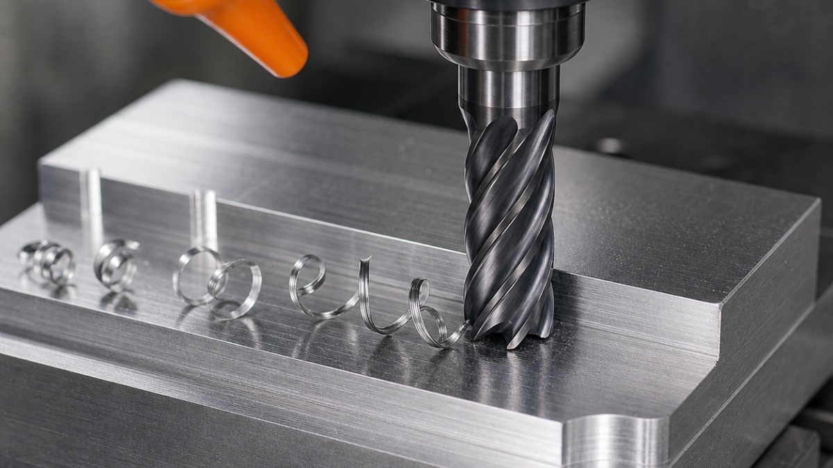
English: Feed per Tooth in CNC Milling: Chip Load, Radial Thinning and Runout
Feed per tooth is fz = feed/(rpm × engaged flutes), but that arithmetic alone does not describe the chip. At low radial engagement the maximum chip thickness is smaller than programmed fz; with runout, one flute may take more than its share; during a ramp, not every flute sees the same load. The practical target is a repeatable chip thick enough to cut above the edge hone without exceeding edge strength.
Separate programmed fz from actual chip thickness
Use the number of cutting flutes, not every visible land. Confirm the controller feed unit and whether the CAM feed is centerline feed around arcs. A 10 mm, four-flute cutter at 8,000 rpm and 960 mm/min has fz=0.030 mm/tooth. That is only the programmed value. If ae is 0.5 mm, radial chip thinning applies; if runout is 8 µm, the heavy flute can receive a large share of a small nominal chip.
For a small indexable pocket cutter, start with the maker’s effective tooth count and confirm how much chip space remains in a confined cut. The APMT1135 small-diameter pocket example connects those feed decisions to cutter diameter, insert seating and the choice of a separate corner-finishing tool.
| Drawing/toolpath condition | Feed-per-tooth action | Tool decision | Evidence |
|---|---|---|---|
| Full slot, ae=100%D | No thinning compensation; derate entry and chip evacuation | Fewer flutes and polished gullets for aluminum; strong 4-flute for steel | Chip packing, spindle load, exit burr |
| Adaptive roughing, ae=5–10%D | Apply maker/CAM thinning factor, keep engagement constant | Radius end mill, variable helix, stable hydraulic/shrink holder | Chip thickness consistency and notch line |
| Thin-wall finish, ae<3%D | Do not chase theoretical compensation if wall deflects | Sharp dedicated finisher, short reach, low runout | Released wall size, taper and waviness |
| Helical ramp or bore | Use ramp feed factor and verify axial-edge capability | Center-cutting tool with adequate gash and coolant path | Thrust, floor witness and bore cylindricity |
A correction ladder prevents double compensation
First take fz and Vc from tool-maker data for the exact grade and material condition. Second calculate rpm and linear feed. Third apply radial-thinning correction once—either in CAM or manually, never both. Fourth reduce for entry, overhang, weak fixturing and interrupted cuts. Fifth respect machine acceleration: a short segment may never reach the commanded feed. Record both commanded and measured cycle behavior so a future operator does not add a second correction.
Runout defines the minimum useful chip
Measure at the cutting edge after the tool is assembled. If total indicated runout approaches a meaningful fraction of fz, one edge rubs while another overloads. Clean the taper, inspect the collet, shorten projection and index the tool before raising feed. Diameter wear compensation cannot repair unequal flute loading. A small-diameter finisher may need a lower-runout holder rather than a larger nominal fz.
Validate roughing and finishing differently
For roughing, trend spindle load, chip evacuation, flank/notch wear and material removal stability. For finishing, measure size, wall release, Ra and burr height; the finish pass may intentionally use a smaller fz but must still cut. Inspect after unclamping where thin features are involved. Reject a feed change if it improves sound but worsens single-flute wear, taper or burrs.
Related: cutting-parameter selection workflow; runout measurement and correction; constant-engagement milling.
Feed-per-tooth FAQ
Does doubling flutes double feed? Only if chip space, power and dynamics still permit the same fz. Should radial thinning be corrected in a slot? No; ae is full diameter. Can sound set fz? Sound is a clue, not a measurement; pair it with load, chips, runout, wear and part results.
Direction check: Feed per tooth is not independent of cutting direction. Compare entry load, backlash sensitivity and wall-spring behavior in the climb-versus-conventional milling guide before treating a direction change as a simple sign change in CAM.


