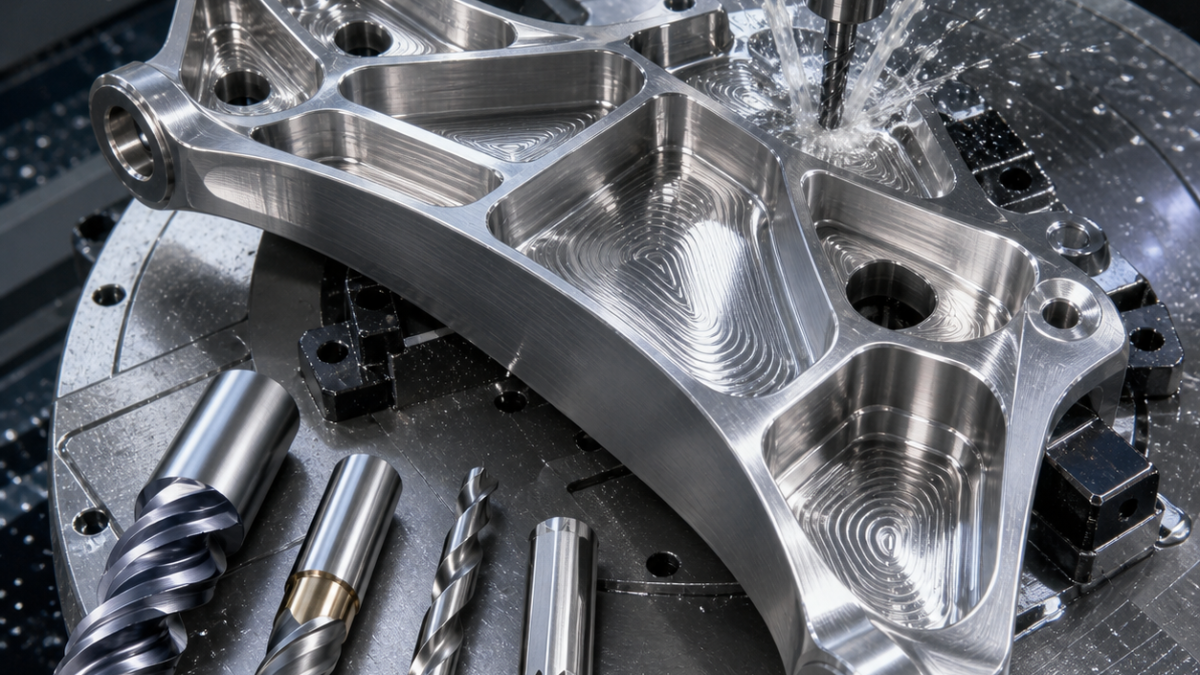
English: Ti-6Al-4V Aerospace Bracket Tooling for Thin Ribs and Heat Control
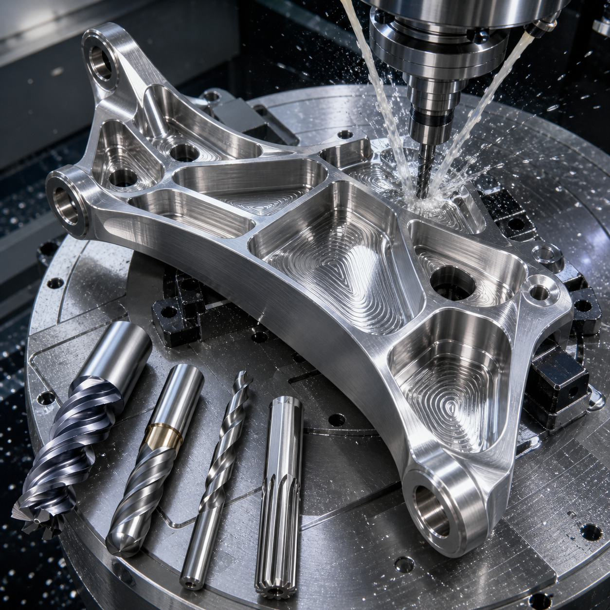
A titanium aerospace bracket CNC machining plan must balance material removal, heat control and thin-feature stability. This Ti-6Al-4V drawing includes deep pockets, thin ribs, filleted corners and precision holes. The process uses rigid fixturing, constant-engagement roughing and staged finishing so that heat and residual stress do not distort the final geometry.
Drawing Review and Risk Features
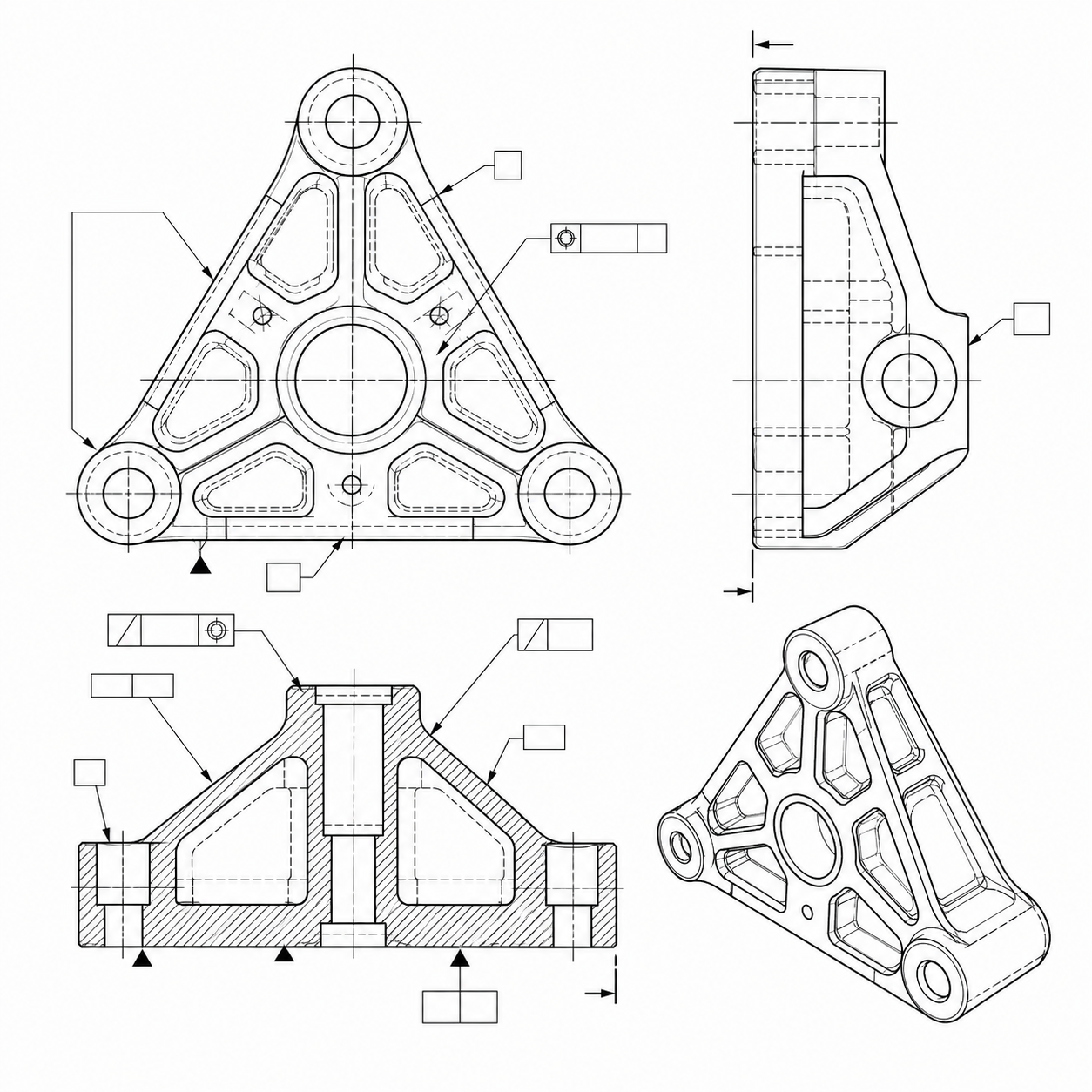
Start by identifying load-path surfaces, datum holes, minimum rib thickness, corner radii and inaccessible undercuts. Keep the part supported by a stable outer frame during early operations. Do not finish the thinnest ribs while large amounts of stock remain elsewhere. Critical holes should be machined after the surrounding pockets have reached a stable semi-finished state.
Carbide Tooling and Heat-Control Plan
- Roughing: a variable-helix, unequal-pitch carbide end mill with a titanium-appropriate coating. Use adaptive or trochoidal paths with controlled radial engagement.
- Semi-finishing: a rigid corner-radius end mill leaves a uniform finishing allowance and strengthens the cutting edge.
- 3D fillets: a ball nose end mill with a short overhang; select step-over from the required scallop height.
- Precision holes: carbide drilling with through-tool high-pressure coolant, followed by reaming or finish boring according to diameter and positional tolerance.
- Edges: a sharp chamfer tool and controlled deburring prevent local bending of thin ribs.
Recommended Operation Sequence
- Face the stock and establish datums with a rigid fixture.
- Open pockets using constant-engagement roughing and high-pressure coolant.
- Alternate opposing pockets to balance heat and stress.
- Semi-finish ribs and walls while retaining support tabs or a stable frame.
- Machine critical holes from the inspection datum system.
- Finish 3D fillets, ribs and datum faces with minimal tool overhang.
- Deburr, clean, allow temperature normalization and perform CMM inspection.
Cutting data must come from the actual tool manufacturer and machine condition. In titanium, rubbing is costly: keep chip load stable, avoid dwell, evacuate chips and replace a degrading tool before notch wear damages the surface. Record tool life by actual cutting time and inspect the edge at planned intervals.
Choose the next tool by what still supports the rib
This is a hypothetical process study, not a flight-qualified manufacturing instruction or a reported customer result. Before adopting the illustrative tool sizes below, check the released drawing’s minimum radius, reach and holder envelope. Specify a tough fine-grain carbide grade approved for Ti-6Al-4V, a supplier-qualified PVD coating where appropriate, and only the edge preparation needed to resist the planned entry load. A heavier hone is not automatically better for a slender rib.
| Drawing feature and state | Tool candidate | Hold point |
|---|---|---|
| Pocket with outer frame retained | Ø10, four-flute variable-helix corner-radius carbide rougher; short hydraulic holder | Verify chip space, coolant access and actual overhang before adaptive entry |
| Paired rib walls after bulk removal | Ø6 short corner-radius semifinisher; separate sharp finishing edge | Map residual stock on both sides; do not let one full-width remnant push the rib |
| 3D fillet | Ø4 two-flute ball nose with minimal reach | Check effective cutting diameter and scallop; avoid treating the zero-speed tip as a productive cutting zone |
| Precision locating hole | Through-coolant carbide drill, then fine boring if position needs correction; reaming only with a satisfactory pre-hole | Confirm access and datum transfer after pocket semifinishing |
| Small edge break | Short Ø6 two-flute 90° chamfer mill if the drawing specifies a 45° chamfer | Inspect width without removing the adjacent functional land |
Keep support close to the current cut rather than increasing clamp load across an unsupported span. Alternate paired-wall operations while useful backing stock remains. Record rib thickness at the base, middle and top in the fixture, then repeat at matching locations after controlled release and temperature stabilization. If the change exceeds the drawing allowance, investigate restraint and stock sequence before adjusting cutter compensation. Hole size, position, wall profile and Ra require their own measurements; a smooth-looking rib is not an acceptance result.
Use the titanium milling tool-selection guide for material and wear decisions, and the cutting-parameter decision hub for the calculation record. Neither substitutes for the actual tool supplier’s limits.
Can one finishing tool handle the wall and every fillet?
Only if access, corner radius and contact geometry all agree. Otherwise keep the wall finisher and ball nose separate so that a local fillet cannot dictate excessive reach for the whole wall.
Does a correct size in the fixture prove the rib is finished?
No. The specified acceptance state governs. Compare clamped and released measurements using the same datum logic before accepting a compensation change.
FAQ
Why is constant engagement important in titanium milling?
It limits sudden chip-thickness and heat spikes, helping stabilize tool load and reduce edge chipping in corners.
When should thin ribs be finished?
After major stock removal and semi-finishing have stabilized the part. Keeping temporary support longer reduces vibration and distortion.
Related CNC Tooling Cases
Compare this process with the drawing-based aluminum bracket plan, the titanium milling heat-control guide and the 5-axis tool-orientation article.
For the general heat-control logic behind this bracket case, see titanium milling tool selection and tool-life guide.


