English: Case Overview
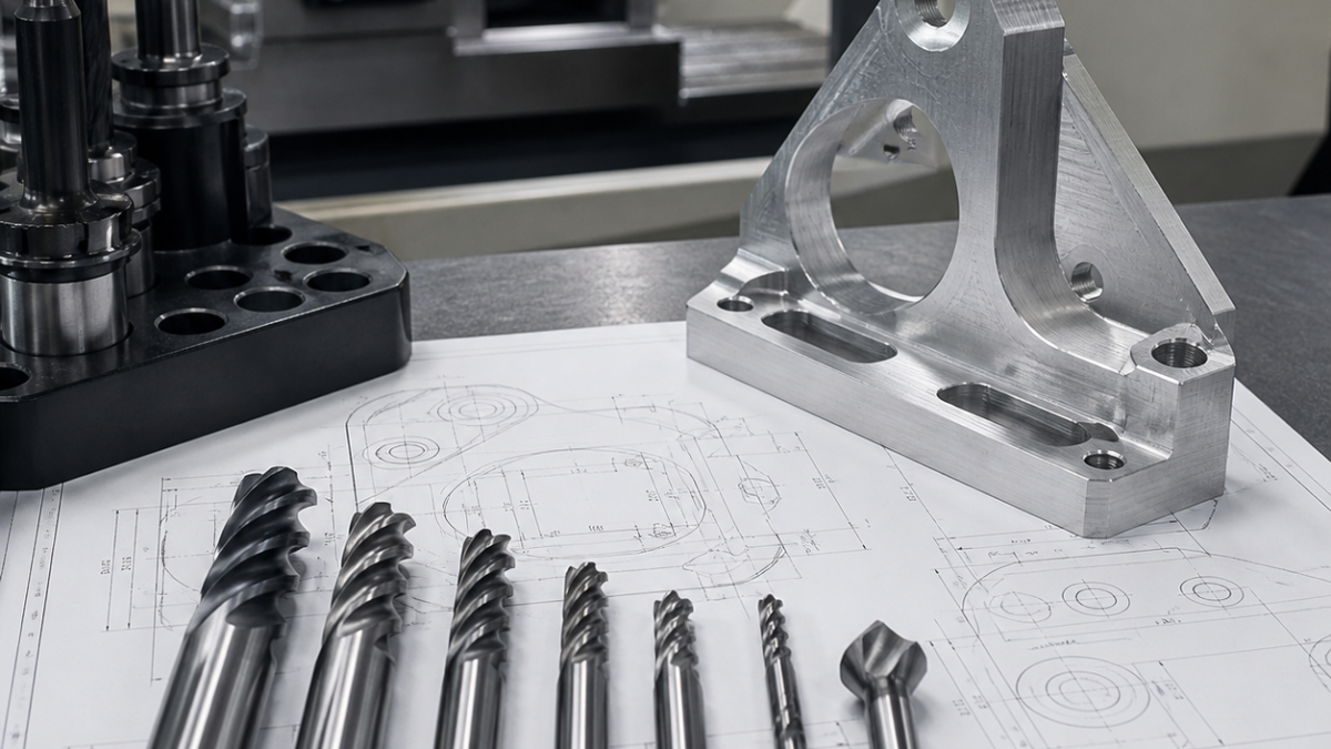
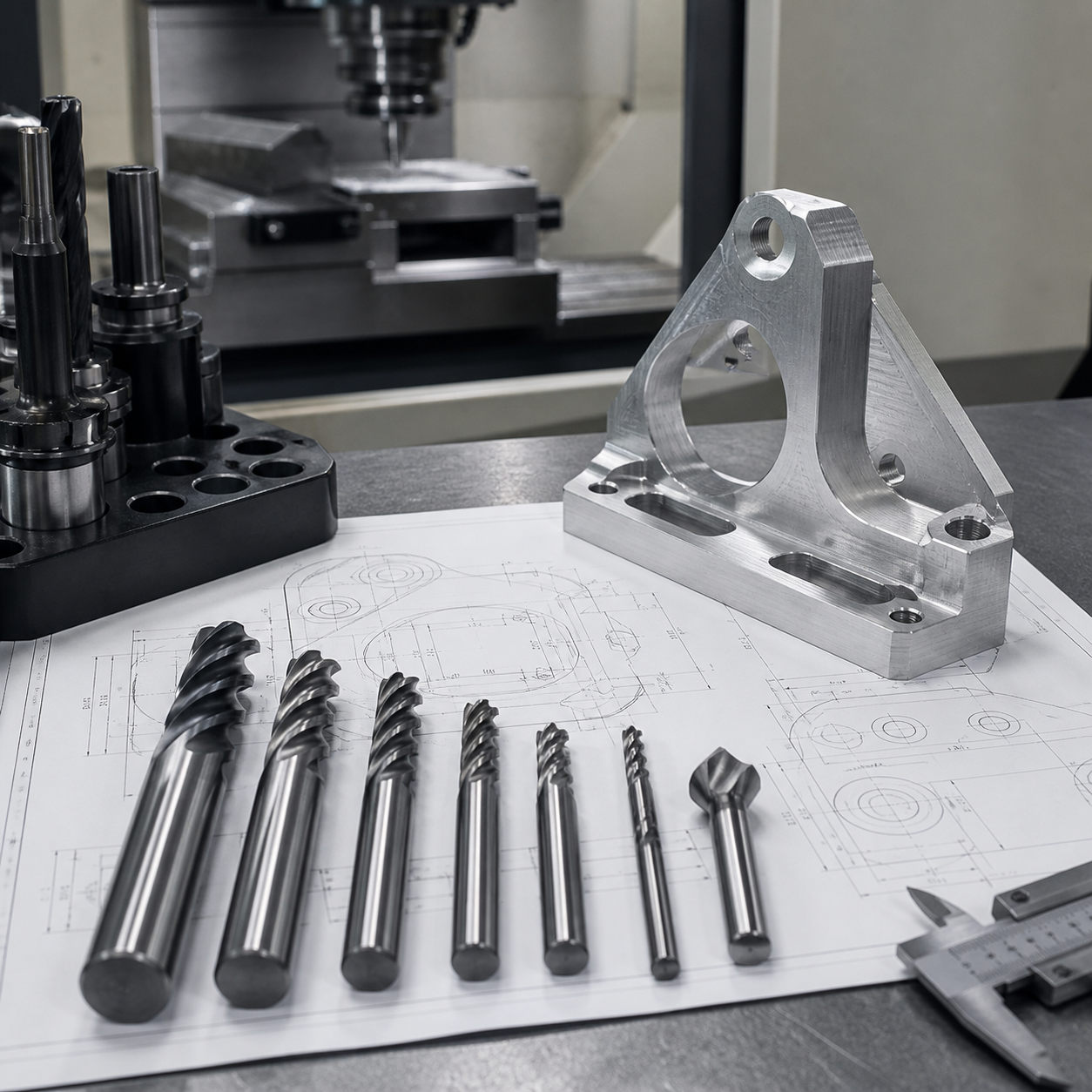
This hypothetical aluminum bracket case starts from a typical drawing with pockets, through holes, chamfered edges and a flat mounting surface. The goal is to build a practical CNC tooling plan that balances cycle time, surface finish and dimensional stability without overcomplicating the process.
The suggested tool set includes a carbide roughing end mill for pocket removal, a finishing end mill for wall and floor quality, a carbide drill for through holes, and a chamfer mill for edge breaks. If the drawing includes tight flatness or thin ribs, the fixture should support the bracket near cutting zones instead of clamping only at the ends.
Tooling and Process Plan
Rough the pockets first with stable radial engagement, then leave a controlled finishing allowance. Drill holes after major roughing so the part has relaxed before final sizing. Finish critical walls with a sharp carbide end mill and use a light chamfer pass to reduce hand deburring.
SEO Machining Takeaway
For aluminum bracket drawings, the best tooling solution is usually not the largest tool list. It is a balanced plan that matches pockets, holes, chamfers and tolerance zones to the right carbide tools.


