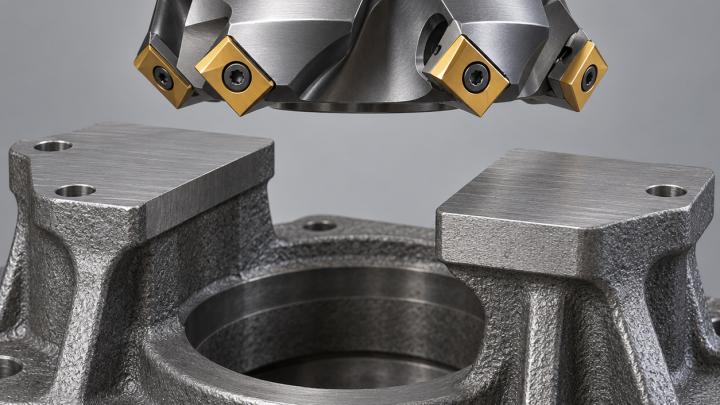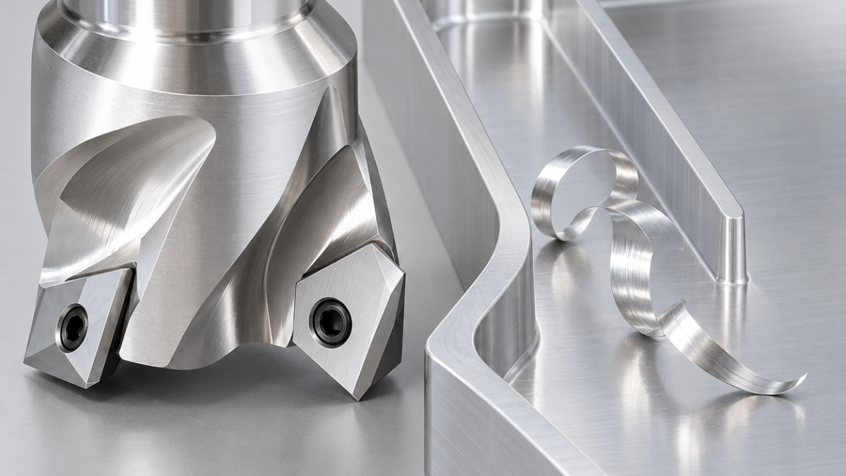
English: APGT1604 Aluminum Inserts for Thin Ribs and Clean Chip Flow
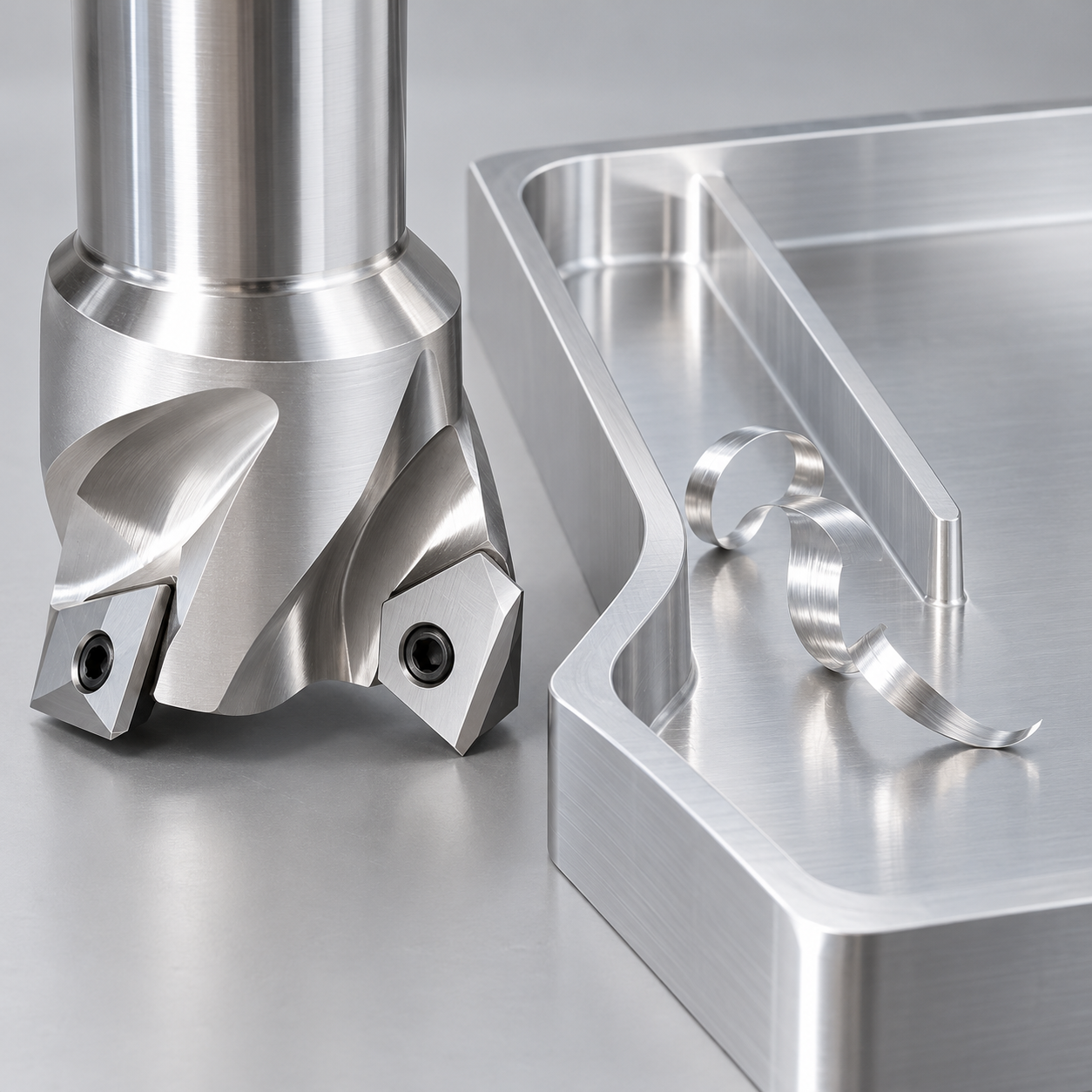
For low-silicon aluminum, a polished, sharp APGT1604 aluminum geometry can be more appropriate than a heavily prepared steel-milling edge. That is a geometry-and-grade choice, not a claim that every APGT is uncoated or that every coating is unsuitable. The hypothetical component is a 6061-T6 instrument tray with 12 mm-high ribs finished to 2.5 ±0.05 mm. The insert cutter opens the channels while a smaller solid tool controls the flexible rib.
Start with the rib that will be left standing
Plan both sides together. If one channel is fully finished while the opposite side still holds heavy stock, the rib’s stiffness changes before its final pass. The example specifies Ra 1.6 μm on locating faces, an R1 maximum wall-floor blend and a restrained 0.2 mm edge break. An approved APGT1604 R0.8 option fits the root allowance; its nominal size does not certify another maker’s seat. Verify complete body compatibility and screw details.
Pair low cutting force with a real chip route
| Feature | Tool specification | Reason to avoid an alternative |
|---|---|---|
| Open channel roughing | Ø25 two-tooth aluminum shoulder cutter approved for APGT1604; polished positive geometry, sharp edge, uncoated fine-grain carbide grade specifically offered for low-silicon aluminum. | A heavy steel-edge hone increases force and can promote smearing at low chip thickness. |
| Flexible rib sides | Ø8 three-flute polished solid-carbide aluminum end mill, small corner radius within R1; precision collet and minimum reach. | A large indexable body is not the only choice just because it fits the opening. |
| Accessible floor strips | Indexed sharp APGT edge, light qualified pass, axial runout checked. | Do not reuse an edge with adhered aluminum for a cosmetic or locating floor. |
| Top rib edge | Ø6 two-flute sharp carbide chamfer mill, 90°, minimal contact. | A broad chamfer removes too much material from the 2.5 mm rib. |
A balanced sequence for a compliant wall
Hold the tray on its thick base with low-distortion perimeter clamping. Rough alternating channels in stages, keeping stock on both rib faces; start with about 0.25 mm per side for the trial. Semifinish both sides before committing to the last cut. Control radial engagement on the final contour and choose the cutting direction so force is supported where possible. Do not use a long-flute tool when only 12 mm of wall needs access.
Direct compatible lubricant and coolant so chips leave the active channel, not toward the finished rib. Polished flutes do not make recutting harmless. Select speed from the insert supplier’s range and the body’s maximum rpm, with spindle power, balance and holder limits checked. Feed must create a clean chip; repeated near-zero passes can smear aluminum. If built-up edge appears, stop to examine lubrication, runout and chip thickness before blaming the alloy.
Two measurements distinguish bending from an offset error
Measure rib thickness high and low while lightly supported, then measure again after unclamping and temperature stabilization. A consistent offset differs from a tapered or bowed rib. Check base flatness, root clearance and top-edge burrs separately. Do not scrape a burr into the locating surface. For chip management compare aluminum evacuation and finish; for an abrasive-alloy alternative see when PCD changes the tooling decision.
APGT aluminum-tool questions
Can APGT1604 replace APKT1604 in any body? No. Similar outlines do not prove thickness, hole, support or edge-envelope compatibility.
Is uncoated always best for aluminum? No. This choice addresses the stated low-silicon alloy and sharp-edge duty; abrasive high-silicon material can justify a different grade or PCD.
Manufacturer reference: dimensions and system compatibility.