English: Case Overview
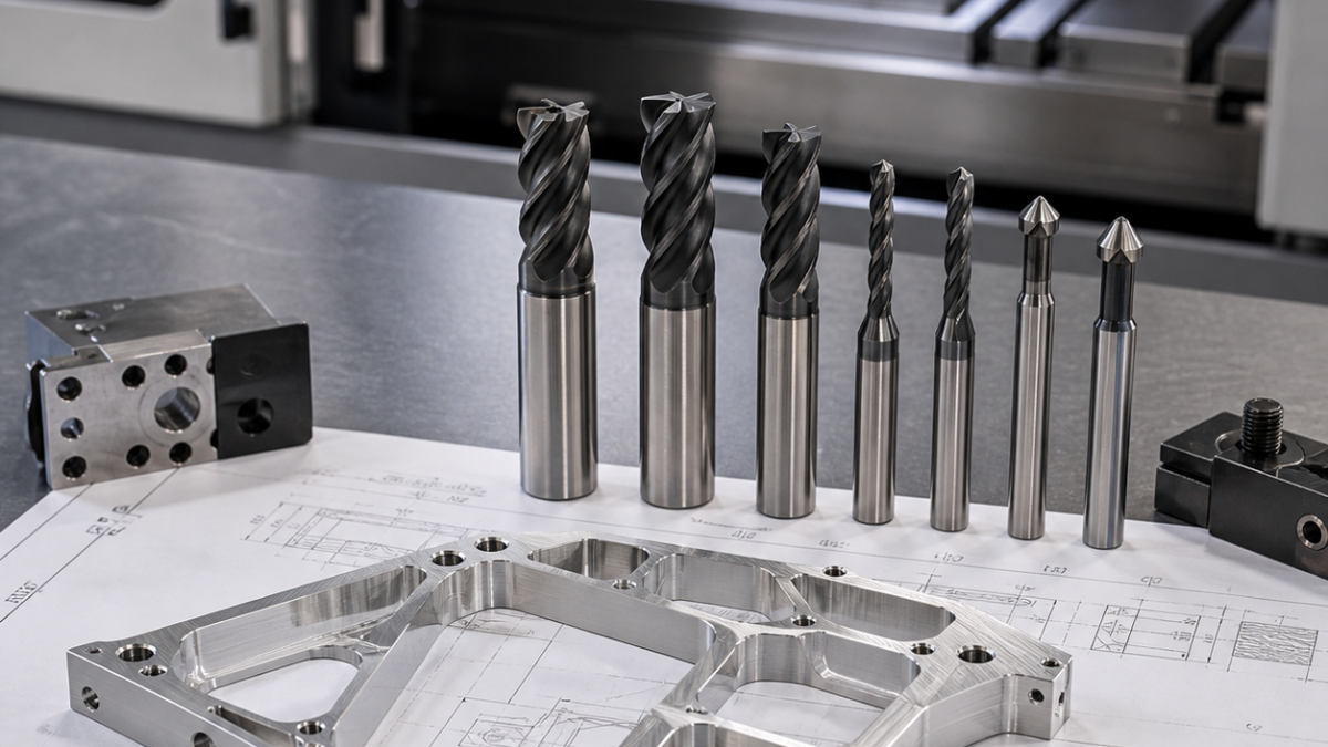
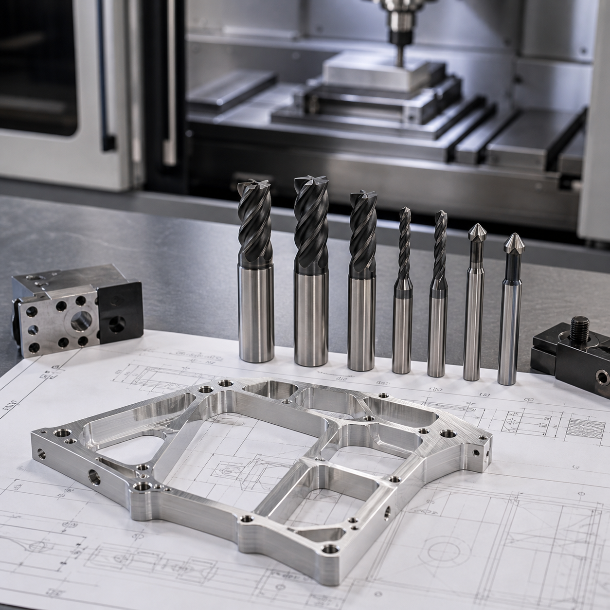
This hypothetical thin-wall aluminum frame drawing includes ribs, pockets, mounting holes and flatness requirements. The main challenge is not only material removal, but keeping the frame from vibrating or moving after roughing. A drawing-based CNC tool selection plan should match every feature to the right cutter, fixture support and finishing sequence.
The recommended tool set includes a high-efficiency carbide end mill for roughing pockets, a sharp finishing end mill for thin walls, carbide drills for mounting holes and a chamfer mill for burr control. If the frame has large open areas, temporary support tabs or staged machining can help reduce distortion.
Tooling and Process Plan
Start with balanced roughing on both sides of the frame when possible. Leave a uniform finishing allowance on thin walls, then finish critical ribs with light radial engagement. Final holes and chamfers should be completed after major stress release, so the drawing tolerances remain more stable.
Machining Takeaway
For thin-wall aluminum frame machining, fixture support and machining sequence matter as much as tool choice. A good tooling plan prevents the cutter from solving one problem while creating distortion elsewhere.


