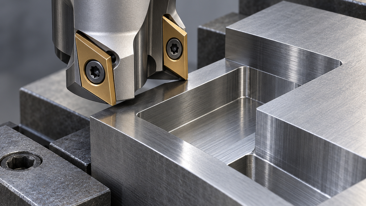
English: APMT1135 Insert Selection for Small-Diameter Pocket Milling
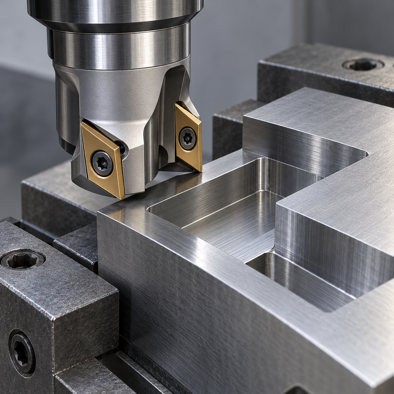
For a small indexable pocket cutter, choose an APMT1135 insert only after checking the cutter seat and usable cutting edge. The practical advantage is replaceable roughing edges in a compact body—not permission to plunge or finish every corner. This hypothetical case uses a normalized medium-carbon-steel clamp jaw with a 28 mm open pocket, 12 mm depth and R4 internal corners. The purchase decision is whether a 16 mm, two-tooth APMT1135 cutter can remove the bulk without crowding the chip path.
What the 28 mm opening rules out
A 25 mm cutter can enter geometrically but leaves little freedom for an arc entry and chip escape. A 16 mm body leaves room to control engagement. Its 8 mm radius cannot produce the R4 corners; pretending otherwise moves the error into inspection. The drawing also specifies pocket width ±0.03 mm, floor Ra 3.2 μm and a 0.3 mm edge break. Treat these as separate operations. A reference such as BAP300R is useful for searching, but the full body code, insert suffix, screw and seat drawing must agree before assembly.
Feature-to-tool allocation
| Feature | Tool choice | Decision boundary |
|---|---|---|
| Open pocket bulk | Ø16, two-tooth indexable cutter; APMT1135 steel geometry, tough PVD-coated carbide, modest edge hone; short mechanical side-lock holder if the shank permits. | Two teeth preserve chip space. A heavily honed edge or extra-dense pitch can raise load on a small spindle. |
| Walls and R4 corners | Ø6, four-flute fine-grain carbide end mill, steel coating, small corner radius within the drawing allowance. | Rest-machine before the final contour; a full-width corner cut overloads the finisher. |
| Pocket floor | Clean indexed APMT edge with measured axial runout, light controlled finishing pass. | If insert-height spread leaves unacceptable steps, use the solid end mill; do not compensate one high tooth with deeper cutting. |
| Edge break | Ø6, two-flute 90° carbide chamfer mill, short projection. | Chamfer only after pocket size is accepted; no sharp-edged square corner is required. |
Keep roughing chips out of the final wall
Grip a sacrificial lower land in supported soft jaws and leave the pocket mouth unobstructed. Enter from the open end, use constant-engagement arcs, then clear chips before semiclosing turns. Divide the 12 mm depth into levels within the body’s catalog limit; insert length is not permissible axial depth. Leave approximately 0.20 mm radial stock as a trial allowance, measure the rough pocket, and adjust before finishing. Do not use axial plunging unless the exact cutter is rated for it.
Set cutting speed and feed from the selected grade’s steel range, then account for engagement. For illustration, 3,000 rpm × 2 teeth × 0.06 mm/tooth equals 360 mm/min; this is a calculation example, not a validated setting. Intermittent coolant on a hot edge can aggravate thermal damage. Follow the insert supplier’s wet/dry recommendation and maintain consistent delivery. Stop for chip packing, edge chipping or a rising load trend rather than waiting for a broken screw.
Acceptance before changing to a cheaper insert
Measure width at the mouth and back, wall taper at two heights, floor steps and the corner blend after deburring. A burr can make a pin check look tight while the pocket is oversized. Record which indexed edge was used and inspect the seat for fretting. Compare holder runout checks with feed-per-tooth calculations before changing grade.
APMT1135 questions from the tool crib
Will every APMT1135 fit a 300R body? No. Verify the manufacturer’s compatibility list, seat contact and screw specification; the short label is not an approval.
Can it replace a solid end mill entirely? Not here. The insert cutter removes accessible stock, while the smaller solid tool establishes the R4 geometry and controlled wall finish.
Manufacturer reference: dimensions and system compatibility.


