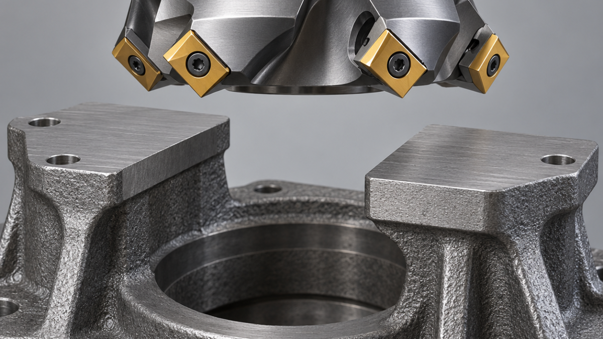
English: SEKT1204 Inserts for 45-Degree Face Milling: Pads and Flatness
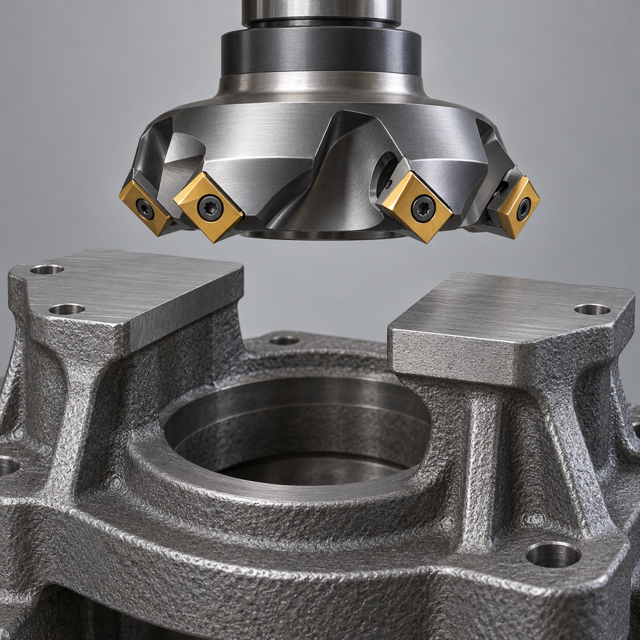
SEKT1204 inserts in a compatible 45-degree face mill are a practical option for open mounting pads, not for producing a true 90-degree wall. The body sets the entering angle; the square insert alone does not. In this hypothetical gray-iron pump base, two pads separated by a central opening must share a mounting plane. The main selection issue is whether the fixture can absorb the axial force without making a flat-looking clamped part spring out of tolerance.
From pad drawing to cutter assembly
| Drawing feature | Assigned tool | Rejected shortcut |
|---|---|---|
| Two open pads, 42 mm wide | Ø63 compatible 45° shell mill, moderate pitch, four SEKT1204 edges engaged by a verified body design; cast-iron carbide grade, wear-resistant coating where recommended, reinforced but not blunt edge. | More teeth do not help if interruptions and fixture compliance dominate. |
| Common final plane | Same cutter with clean indexed edges and checked axial runout; short face-contact arbor. | Do not fit an unapproved wiper insert or compensate a high tooth by increasing feed. |
| Bolt-head spotfaces near a wall | Ø12, four-flute coated carbide end mill, flat end, short reach. | The 45° cutter would leave a sloped boundary or hit the adjacent wall. |
| Pad perimeter burrs | Ø8 two-flute carbide chamfer tool, light edge break within the print. | Uncontrolled rounding reduces the usable contact pad. |
The first setup decision is underneath the casting
Seat the casting on three defined supports; place clamps over supported load paths. Extra adjustable supports may stabilize thin regions but must not jack the part into a new shape. The study requires pad coplanarity 0.04 mm and Ra 3.2 μm. Record the casting condition and hardness before assigning cutting data; a clean gray-iron skin and a hard inclusion are very different loads.
Remove the casting skin with a grade and edge preparation rated for that condition. Rough both pads in a balanced sequence, leave about 0.25 mm trial finishing stock and release the clamps to check movement before the final setup. For the finish pass, use an offset path that avoids a symmetric entry where practical. When crossing the opening, assess re-entry on the second pad; do not use only the average spindle power to judge tooth loading.
Surface finish is not an insert-count contest
Choose tooth count from spindle torque, number of teeth in contact and interruption severity. Use the body’s rated speed and the selected grade’s cutting range. An axial-height error can leave one insert doing most of the finishing. Clean the seats, verify the arbor face and inspect each cutting corner. If the coating wears gradually, reassess speed; isolated chips after the gap point toward impact, seat movement or local casting defects.
Use suitable enclosure extraction for gray-iron dust and protect guideways. Follow the grade supplier’s dry/wet strategy; occasional coolant splashes are not a controlled thermal process. Clear loose grit before measuring or locating the opposite face. Keep any burr removal off the actual mounting plane.
Inspect after the load is removed
Check pad heights on a surface plate or by a datum-based CMM routine after unclamping, using points near both edges and the opening. A straightedge on one pad cannot establish their common plane. Inspect roughness at the interruption boundary as well as the center. Related checks: fixture stiffness and chatter; tool assembly runout.
SEKT face-milling questions
Can this cutter finish a square internal corner? No: the specified 45° assembly leaves a different geometry; use a shoulder tool for the wall.
Why is flatness worse after loosening the clamps? The cutter may have machined a deflected casting flat. Recheck support locations and clamp force before buying another insert grade.
Manufacturer reference: dimensions and system compatibility.


