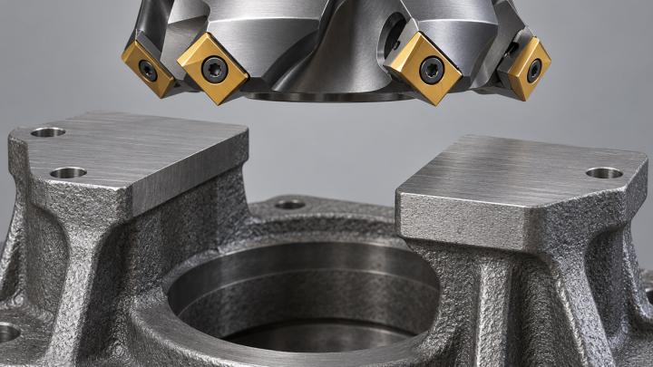
English: LNMU0303 High-Feed Inserts: CAM Radius and Finishing Stock
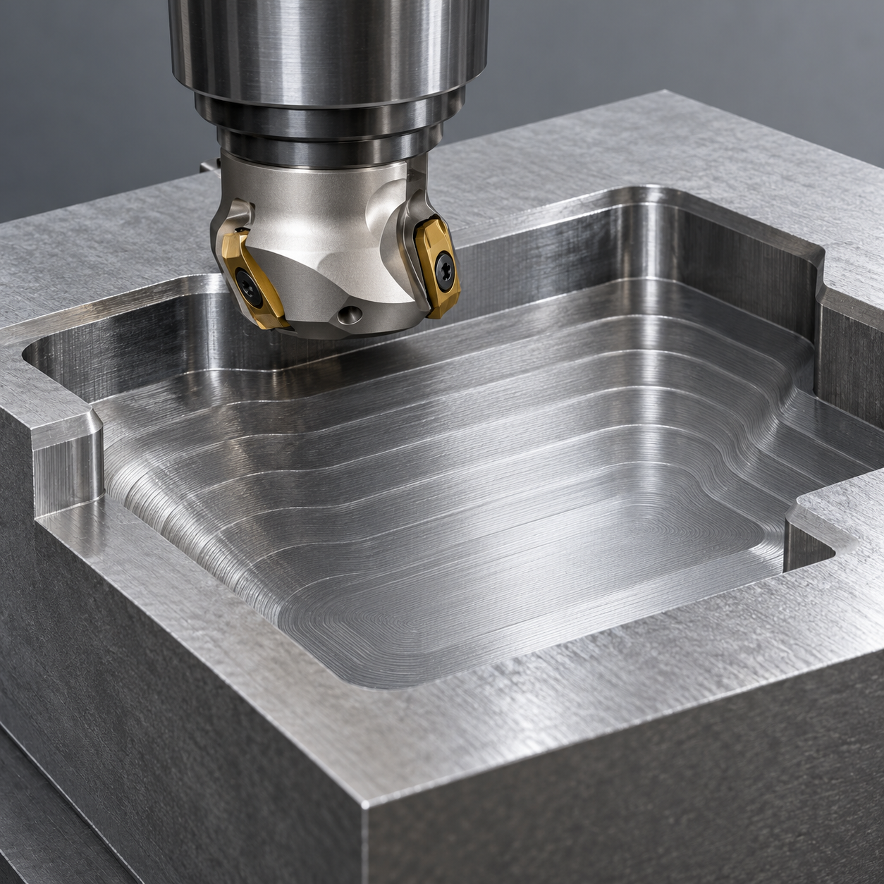
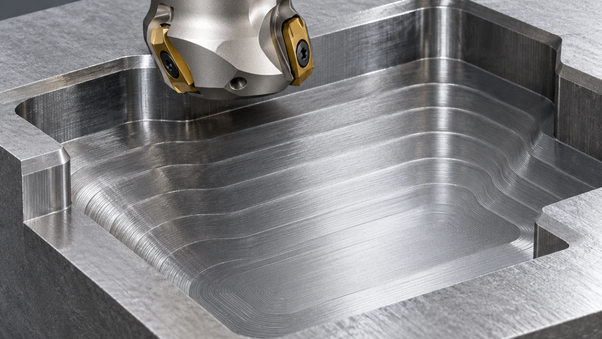
Choose LNMU0303 when shallow-layer roughing suits the part and machine, but load the exact insert geometry into CAM before using a high-feed program. “0303” is not a universal depth limit or virtual corner radius. This hypothetical 40 mm-thick prehardened mold plate has an 80 × 60 mm pocket, 24 mm deep, a flat floor and R5 internal corners. The high-feed cutter removes volume; a separate finishing tool creates the vertical walls.
Three numbers that must not be copied from another program
The programmed corner representation, maximum axial depth and allowed ramp angle belong to the actual body/insert combination. Tungaloy’s DoFeed catalog distinguishes LNMU03 ZER and UER geometries; their limits are not identical. A simulation using a generic toroidal tool can show enough stock while the physical insert cuts a different envelope. Check both the nominal drawing and the toolmaker’s recommended CAM definition.
Build the roughing and finishing chain
| Pocket requirement | Tool allocation | Boundary |
|---|---|---|
| Bulk stock in shallow layers | Verified Ø20 four-tooth LNMU03 body, LNMU0303 grade and geometry for prehardened steel; coated tough carbide with factory edge preparation; shortest collision-free holder. | Do not assume an insert from another suffix preserves the same sweep or depth limit. |
| Wall stock and R5 corners | Ø8, four-flute coated carbide corner-radius end mill; small R0.5 corner, reduced engagement. | High-feed inserts do not leave a true square wall/floor junction. |
| Flat floor finish | Same Ø8 solid tool or a separately qualified flat-end finishing cutter, low axial stock, verified runout. | Do not call the rougher’s shallow scallops a finished datum. |
| Top-edge break | Ø6 two-flute carbide chamfer mill, 90°. | Deburr only after wall size and corner cleanup are accepted. |
Check remaining stock in both the model and the part
Support the plate under the pocket and clamp its outer frame. For a first trial, program 0.4 mm layers only if the chosen assembly permits them; this is a hypothetical depth, not a universal LNMU setting. Leave 0.4 mm normal stock and inspect the residual model at the wall toe. Semifinish the corners and floor transition before the Ø8 final pass. Simulate holder clearance through the full 24 mm descent.
Use the selected grade’s speed and chip-load range, not a conventional 90° shoulder-mill feed. A shallow entering angle reduces chip thickness, but a large numeric feed is justified only by actual geometry and engagement. Check the machine’s acceleration and achievable feed in short moves; repeatedly braking in corners can turn a nominal high-feed operation into rubbing. Favor smooth linking and avoid dwelling against prehardened steel.
Where the trial can fail
More axial loading does not mean zero radial force or unlimited reach. Watch holder movement, vibration near the pocket bottom and chip recutting. Choose consistent air or coolant delivery according to the supplier’s recommendation and maintain a clear chip exit. Stop for edge fracture, seat damage or unexplained load changes. Do not compensate a chipped insert with a new stock offset.
The example’s final targets are width ±0.03 mm, floor flatness 0.04 mm and Ra 1.6 μm. Measure corners and floor-to-wall stock before finishing, then inspect the released plate. For the underlying mechanics see high-feed engagement principles; for access, see deep-pocket reach and chip removal.
LNMU0303 setup FAQ
Can I copy a ZER program to UER? Not without revalidating the tool envelope, depth, feed recommendations and remaining stock.
Why is the wall oversize after roughing? It may be intentional residual stock from the insert profile. Check the actual envelope before applying a correction intended for a square end mill.
Manufacturer reference: dimensions and system compatibility.