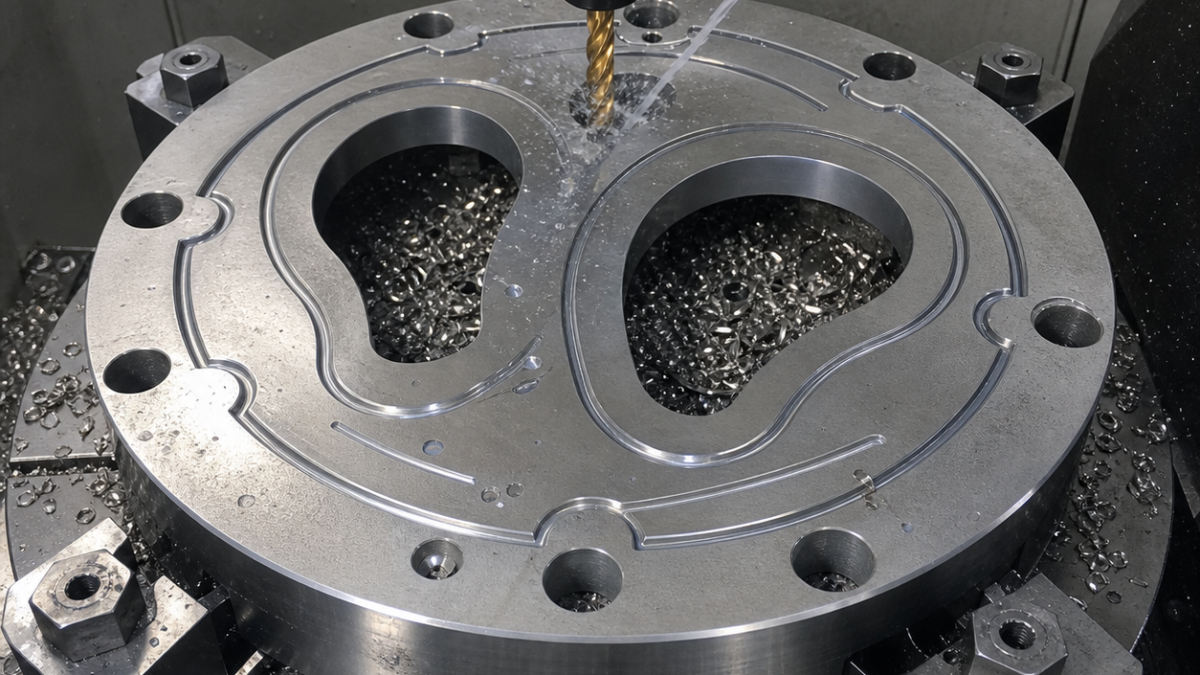
English: Zirconium 702 Pump Wear Plate CNC Tooling Case: Kidney Ports and Seal Grooves
The useful answer for a Zirconium 702 chemical-pump wear plate is to select tools from the sealing geometry outward. The two 18 mm-deep kidney ports need a sharp, open-flute rougher; the 2.2 mm-wide shallow seal grooves need a dedicated short slot tool; and the dowel bores need drilling followed by fine boring so port position is tied to the functional datum frame. This hypothetical case shows that tool map and the process decisions behind it.
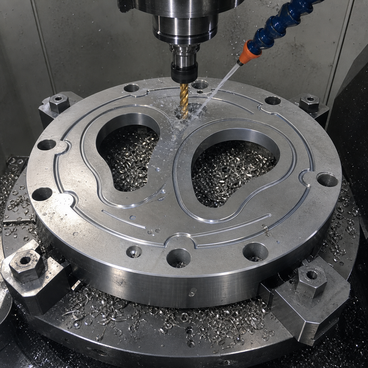
Reading the drawing before selecting cutters
Face A is the pump-side sealing plane. Dowel bores B and C clock the plate, while the center bore is a clearance feature rather than a locating datum. The kidney-port profile is 0.04 mm to A-B-C, the grooves are 0.45 ±0.03 mm deep, the dowels are Ø8 H7, and A requires 0.025 mm flatness with Ra 0.8 µm. A 0.10 mm maximum edge break protects the elastomer without widening the sealing land. Because Zirconium 702 conducts heat poorly and fresh fine chips can be reactive, chip evacuation and edge sharpness are part of the tooling decision, not housekeeping after the cut.
Feature-to-tool selection table
| Drawing feature | Selected carbide tool and holder | Why it wins / rejected alternative |
|---|---|---|
| Datum face A | Ø50 positive-rake face mill, polished uncoated fine-grain carbide inserts, light edge hone, balanced arbor | Low cutting force limits heat and smearing. A negative steel face mill is rejected because it raises pressure at the sealing land. |
| Kidney-port volume | Ø12, 3-flute sharp uncoated micrograin carbide, 35° helix, short flute, hydraulic holder with through coolant | Large gullets clear ductile chips. A 5-flute coated rougher offers too little chip space and can rub when zirconium springs back. |
| Port wall and inside radii | Ø6, 4-flute unequal-pitch polished carbide, 0.2 mm corner radius, reduced neck, 24 mm reach, shrink holder | The corner radius protects the edge during finishing. A long ball nose would leave scallops and unnecessary axial force. |
| 2.2 mm seal groove | Ø2.0, 2-flute polished solid-carbide slot mill, 5 mm flute length, precision collet | A short dedicated tool controls width and floor. Interpolating with the Ø6 cutter cannot reach the drawing radius or groove width. |
| Ø8 H7 dowels | Ø7.5 through-coolant carbide drill followed by a small fine-boring head with positive carbide tip | Fine boring corrects location and size. A reamer is rejected because it follows a misplaced or bell-mouthed pre-hole. |
| Edge break | Ø6, 90° polished two-flute carbide chamfer mill, minimum projection | Programs a measured 0.08 mm break. Manual deburring risks touching the seal land. |
Fixture, roughing, finishing and tool-life logic
Operation one faces A and establishes B-C pilot geometry on a vacuum-assisted plate fixture with three hardened rest pads and perimeter clamps outside the seal zone. Operation two locates on A-B-C with relieved buttons under the ports. Kidney ports are opened by helical entry into sacrificial stock and high-efficiency paths at low radial engagement; 0.30 mm radial and 0.15 mm floor stock remain. Semifinishing uses the Ø6 tool to equalize wall stock before a climb-only contour. The seal grooves are cut last with two depth passes and a full circular exit so the tool never dwells at a corner.
Flood coolant remains continuous, and the enclosure is cleared of unrelated magnesium or steel fines. Chips are kept wet, collected separately and removed before they can form a hot nest; the shop’s zirconium risk assessment and suitable Class D response plan govern handling. A rising spindle load, shiny smeared wall or fuzzy exit burr triggers inspection of edge radius and flute packing. Tools are retired before polishing dullness appears: rubbing can create more heat than a productive cut.
Inspection plan and practical FAQ
After thermal stabilization, a CMM constructs A-B-C, scans both kidney profiles at the top, mid-depth and floor, and checks groove center paths. A fine-bore gauge confirms Ø8 H7 after CMM position verification. An optical comparator measures groove width and the programmed edge break; a profilometer records Ra across A without crossing a port. Flatness is checked in a free, unclamped state.
Should Zirconium 702 be machined with coated or uncoated carbide?
For this interrupted plate geometry, sharp polished uncoated fine-grain carbide reduces rubbing and built-up edge. A coating is not selected merely for heat resistance when it rounds the edge.
Why use a separate 2 mm tool for a 2.2 mm seal groove?
It leaves controlled side stock for a compensated finish orbit and keeps the groove floor independent of kidney-port tool wear.
How are reactive zirconium chips controlled?
Use continuous chip evacuation, segregated wet collection, clean enclosures and the facility’s approved combustible-metal procedure; do not allow fine dry chips to accumulate.
Related process comparisons: sanitary seal-face datum planning and slot burr and datum recovery.
中文: Zr 702泵耐磨板配刀:肾形流道、密封槽与定位孔
这类Zr 702化工泵耐磨板应从密封功能倒推配刀:18 mm深肾形流道用大容屑、锋利的开粗刀;2.2 mm窄密封槽用独立短刃槽刀;Ø8 H7定位孔采用硬质合金钻加精镗,才能把流道位置锁定到功能基准。本假设案例重点不是通用转速表,而是图纸特征与刀具一一对应。
图纸基准与配刀边界
A为泵侧密封平面,B、C为定向定位孔,中心孔只作让位。流道对A-B-C轮廓度0.04 mm,密封槽深0.45 ±0.03 mm,A面平面度0.025 mm、Ra 0.8 µm,密封边只允许最大0.10 mm倒钝。锆导热差,细小新鲜切屑具有反应风险,因此容屑槽、刃口锋利度和排屑方式必须在配刀时确定。
图纸特征—刀具选择表
| 特征 | 刀具与刀柄 | 选择及排除理由 |
|---|---|---|
| A密封面 | Ø50正前角面铣刀,抛光无涂层细晶刀片,轻微刃口强化 | 切削力小;负前角钢件面铣刀会增加挤压和拖抹。 |
| 肾形流道开粗 | Ø12三刃无涂层微粒硬质合金,35°螺旋,短刃,内冷液压刀柄 | 容屑充足;五刃涂层刀易堵屑并在回弹表面摩擦。 |
| 流道侧壁 | Ø6四刃不等分抛光刀,R0.2,缩颈24 mm,热缩刀柄 | 圆角强化刀尖;长球刀会产生扇形刀纹和额外轴向力。 |
| 2.2 mm密封槽 | Ø2两刃抛光硬质合金槽刀,刃长5 mm,精密筒夹 | 短刀稳定控制槽宽和槽底;Ø6刀无法满足小圆角。 |
| Ø8 H7孔 | Ø7.5内冷硬质合金钻+正角精镗头 | 精镗可修孔位;铰刀只会跟随偏斜预孔。 |
| 密封边倒钝 | Ø6两刃90°抛光倒角刀,最短悬伸 | 程序控制0.08 mm,避免手工碰伤密封带。 |
装夹、刀路与风险控制
第一序在三点硬支承和外围压紧的真空辅助夹具上加工A面及B、C预孔;第二序用A-B-C定位,流道下方采用让空按钮。Ø12刀螺旋下刀后以小径向吃刀量动态开粗,每侧留0.30 mm、底面留0.15 mm。Ø6先半精使余量均匀,再顺铣一刀精轮廓。密封槽最后加工,分两层下深并采用连续圆弧退刀,禁止在拐角停留。
冷却液持续覆盖切削区,锆屑单独湿式收集,机内不得混有镁屑或钢屑,并按车间的可燃金属制度配备适用的D类处置方案。负载上升、侧壁发亮拖抹或出口毛刺变软变长,表示刀刃钝化或容屑槽堵塞,应立即查刀,不用降低进给继续摩擦。
检验与搜索常见问题
零件热稳定后,三坐标建立A-B-C,在流道上、中、下三个深度扫描轮廓并测密封槽中心轨迹;精密孔规确认Ø8 H7,光学系统测槽宽和0.08 mm倒角,粗糙度仪避开孔口测A面,平台在自由状态检查平面度。
Zr 702应选涂层还是无涂层硬质合金?
本例优先锋利抛光的无涂层细晶刀具,避免为了耐热而采用钝化过大的刃口。
为什么2.2 mm槽不用2.2 mm成形刀?
Ø2刀可通过补偿轨迹分别控制两侧和槽底,成形刀磨损后会同时改变全部尺寸。
锆屑怎样安全管理?
持续排屑、单独湿式收集、禁止细干屑堆积,并严格执行工厂批准的可燃金属流程。
Français: Plaque d’usure Zr 702 : outils pour lumières réniformes et joints
Sur cette plaque d’usure de pompe en Zirconium 702, les outils se choisissent depuis les surfaces d’étanchéité. Les lumières réniformes profondes demandent une fraise très coupante à grand dégagement; les rainures de joint de 2,2 mm exigent un outil court distinct; les alésages de pion sont percés puis alésés finement pour conserver leur position dans A-B-C.
Lecture fonctionnelle du plan
A est le plan d’étanchéité, B et C orientent la pièce. Le profil des lumières vaut 0,04 mm, les rainures ont 0,45 ±0,03 mm de profondeur, les pions sont Ø8 H7 et A impose une planéité de 0,025 mm à Ra 0,8 µm. La faible diffusion thermique du zirconium impose une arête vive et une évacuation continue des copeaux.
Tableau fonction–outil
| Fonction | Outil et porte-outil | Décision |
|---|---|---|
| Plan A | Fraise Ø50 positive, plaquettes carbure fin polies non revêtues | Faible effort; une géométrie négative pour acier favorise le frottement. |
| Ébauche des lumières | Carbure Ø12, 3 dents, hélice 35°, coupe courte, mandrin hydraulique arrosé | Grand volume de goujure; cinq dents réduisent l’espace copeau. |
| Flancs | Ø6, 4 dents inégales, R0,2, col dégagé 24 mm, fretté | Rigidité et arête protégée; la boule longue est refusée. |
| Rainure 2,2 mm | Ø2, 2 dents polies, coupe 5 mm, pince de précision | Largeur compensable et fond indépendant. |
| Pions Ø8 H7 | Foret carbure arrosé Ø7,5 puis tête d’alésage fin | L’alésage corrige la position; l’alésoir suivrait le trou. |
| Cassé d’arête | Fraise à chanfreiner carbure polie 90° Ø6 | Crée 0,08 mm sans retouche manuelle du joint. |
Gamme, copeaux et durée de vie
Le premier montage crée A et les pilotes B-C sur trois appuis. Le second reprend A-B-C avec du vide sous les lumières. L’ébauche adaptative laisse 0,30 mm aux flancs et 0,15 mm au fond; Ø6 égalise puis finit en avalant. La rainure est usinée en dernier, en deux profondeurs, avec sortie circulaire sans arrêt.
Les copeaux restent mouillés, séparés et évacués selon la procédure locale pour métaux combustibles. Charge croissante, surface brillante étalée ou bavure filandreuse imposent l’arrêt et le contrôle de l’arête: diminuer l’avance avec un outil émoussé augmenterait l’échauffement.
Contrôle et FAQ
La MMT scanne les profils à trois niveaux; le comparateur optique mesure rainure et chanfrein; un alésomètre vérifie H7 et le profilomètre mesure A après stabilisation thermique.
Carbure revêtu ou non?
Ici, un carbure fin non revêtu et poli conserve l’arête la plus vive.
Pourquoi une fraise Ø2 pour 2,2 mm?
Une orbite compensée règle séparément la largeur et le fond.
Comment gérer les copeaux?
Évacuation continue, collecte humide séparée et procédure approuvée pour le zirconium.
À comparer avec les plans d’étanchéité sanitaires et le contrôle des bavures de rainure.
Русский: Плита насоса Zr 702: инструмент для каналов и канавок
Для плиты насоса из Zirconium 702 подбор начинается с уплотнения: почкообразные каналы требуют острой фрезы с большими канавками, узкая канавка 2,2 мм — отдельного короткого инструмента, а отверстия Ø8 H7 — сверления и точной расточки в базе A-B-C.
Что задаёт чертёж
A — уплотнительная плоскость, B и C задают угол. Профиль каналов равен 0,04 мм, глубина канавки 0,45 ±0,03 мм, плоскостность A 0,025 мм при Ra 0,8 мкм. Низкая теплопроводность циркония делает острую кромку и отвод стружки частью выбора инструмента.
Таблица элемент–инструмент
| Элемент | Инструмент | Почему |
|---|---|---|
| Плоскость A | Позитивная фреза Ø50, полированный мелкозернистый карбид без покрытия | Малое усилие; негативная стальная геометрия трёт металл. |
| Черновые каналы | Ø12, 3 зуба, 35°, короткая режущая часть, гидропатрон с СОЖ | Большой объём канавок; пять зубьев мешают стружке. |
| Стенки | Ø6, 4 неравных зуба, R0,2, шейка 24 мм, термопатрон | Жёстко и без лишних гребешков шаровой фрезы. |
| Канавка 2,2 мм | Полированная Ø2, 2 зуба, длина 5 мм | Позволяет компенсировать ширину. |
| Ø8 H7 | Сверло Ø7,5 и головка тонкой расточки | Расточка исправляет положение; развёртка следует отверстию. |
| Кромка | Карбидная фасочная Ø6, 90° | Программная фаска 0,08 мм. |
Маршрут и риск
Первый установ создаёт A и пилоты B-C, второй базируется по ним. Адаптивная черновая оставляет 0,30 мм на стенке и 0,15 мм на дне; Ø6 выравнивает припуск и финиширует попутно. Канавка идёт последней двумя слоями без остановки в углу.
Стружку постоянно удаляют, держат влажной и собирают отдельно по утверждённой процедуре горючих металлов. Рост нагрузки, размазанная блестящая стенка или мягкий заусенец требуют проверки кромки.
Контроль и вопросы
КИМ сканирует каналы на трёх глубинах; оптика проверяет канавку и фаску, нутромер — H7, профилометр — Ra.
Нужно ли покрытие?
Здесь выбран острый полированный карбид без покрытия.
Зачем Ø2 для канавки 2,2 мм?
Компенсированная орбита независимо управляет шириной.
Как обращаться со стружкой?
Непрерывно удалять, собирать влажной отдельно и соблюдать местную процедуру.
См. базы уплотнения и контроль заусенца.


