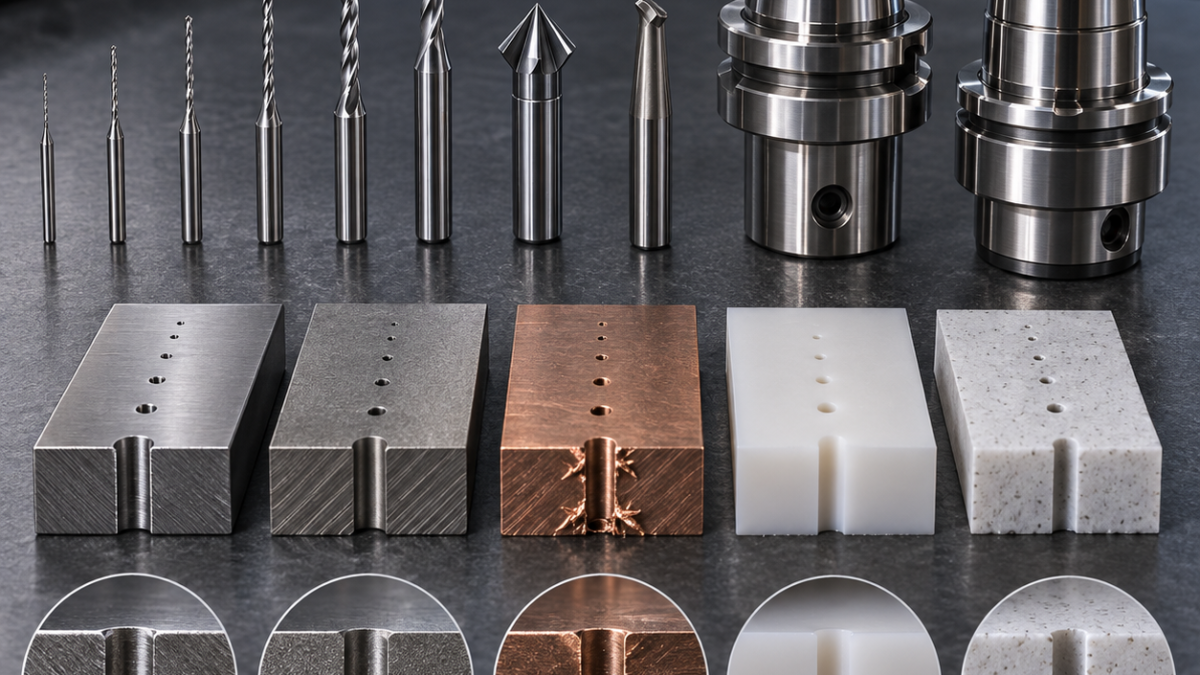
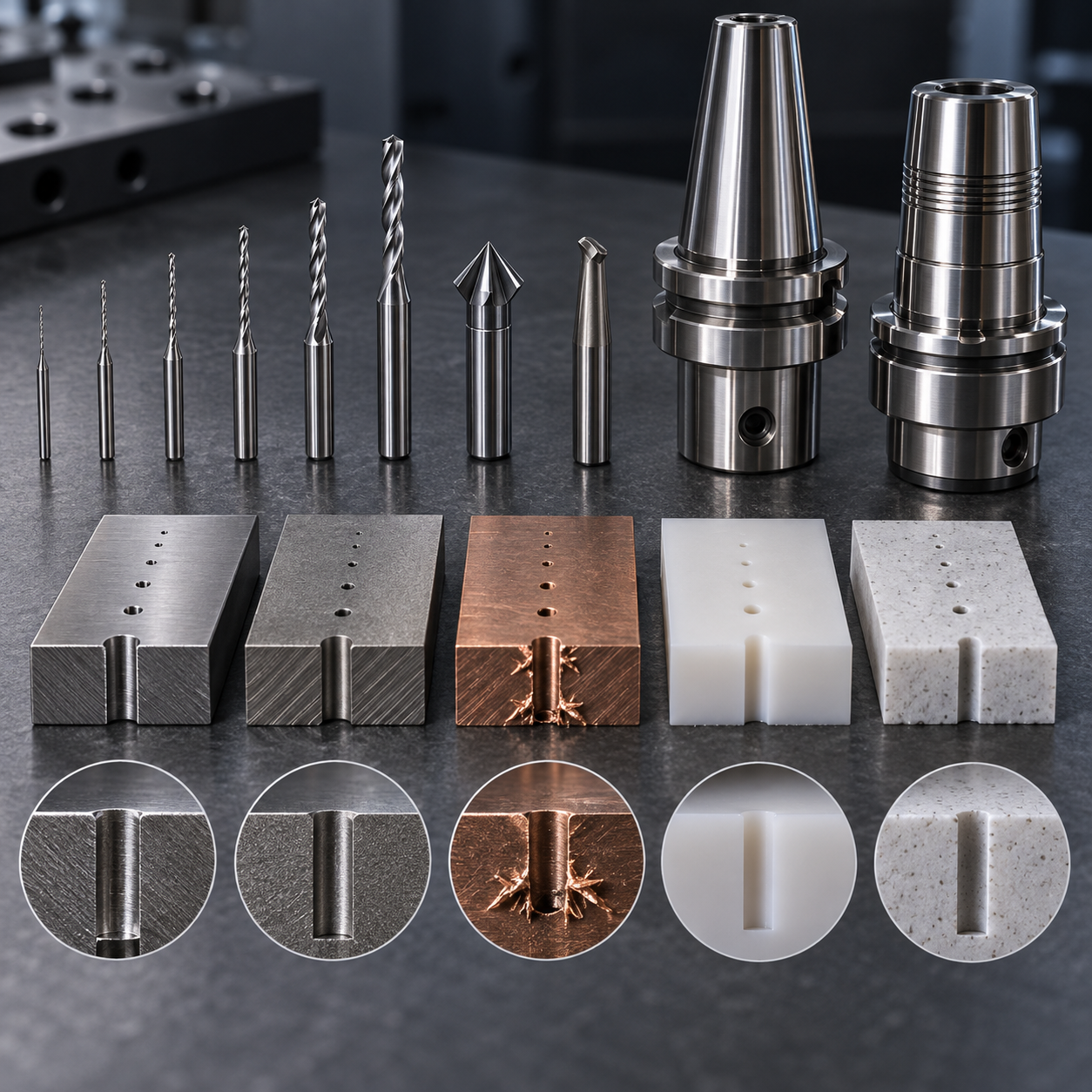
English: CNC Micro-Hole Drilling and Burr Control Tool Selection Guide
The right CNC micro-hole tool is chosen from the drawing’s hole diameter, effective depth, entry angle, exit condition and allowed edge break—not from diameter alone. Start with the shortest micro-grain carbide drill that can reach, keep total indicated runout below the hole’s process allowance, and design chip evacuation and exit support before assigning a deburring operation. This guide turns those decisions into a practical route for holes from roughly 0.18 to 2 mm.
Read the drawing as a micro-hole risk map
Mark every hole as normal-entry, angled-entry, cross-hole, blind, or breakthrough. Then record effective L/D, breakthrough wall thickness, whether the exit is accessible, and whether flow, fatigue, sealing or electrical contact controls acceptance. A 0.6 mm hole through a supported flat plate is not the same process as a 0.6 mm hole breaking into a curved cavity. The second case may need a flat or piloted start, sacrificial backing, a two-sided route, or a qualified reverse-edge tool.
Feature-to-tool selection by material and exit condition
| Drawing condition | Tool, geometry and holder | Why it fits / rejected alternative |
|---|---|---|
| Ductile copper, brass or niobium; clean straight entry | Polished micro-grain carbide drill, 2 flutes, uncoated or DLC/TiB2 after compatibility test; precision collet | Sharp rake and flute polish limit adhesion. A heavily honed AlTiN edge can smear the bore. |
| Titanium or nickel alloy; 4–10×D through hole | Tough micro-grain carbide, 135–140° point, AlTiN/TiAlN where qualified, internal coolant, shrink-fit or hydraulic holder | Edge strength and cooling control heat. A long uncoated general-purpose drill risks rubbing and notch wear. |
| Stainless or cobalt alloy; angled entry or cross-hole | Short carbide spotter or flat mill, then reinforced-point micro drill; optional reverse chamfer tool | The prepared entry prevents skating; blind peck cycles are rejected unless chip exit is proven. |
| FR4 or engineering polymer | Very sharp uncoated carbide or diamond-coated tool for abrasive laminate, large flute space, low-friction holder setup | The edge must cut rather than melt or delaminate. A dense metal-drill geometry retains heat and dust. |
| Alumina or other brittle ceramic | Diamond-coated drill/grinding pin with rigid guide and sacrificial exit support | Controlled abrasion limits chipping. A conventional carbide drill is too wear-sensitive for stable edge quality. |
| Inaccessible internal breakthrough | Supported final ligament, two-sided drilling, qualified abrasive-flow or miniature reverse-edge tool | The drawing’s allowed edge break governs the method. Loose hand wires can ovalize or enlarge the passage. |
Entry, reach and holder decisions
A micro spotter should only create a stable land; a deep conical spot can guide the drill off-axis at an oblique surface. Use a short 120–140° carbide spotter on flat metallic entries, a small flat mill or guide bushing for severe angles, and minimal projection in a shrink-fit, hydraulic or precision collet holder. Reject a general-purpose long drill when its extra reach adds runout and bending without serving the drawing.
Chip evacuation, burr control and tool-life limits
Continuous internal coolant is preferred when the drill supports it, but very small tools may need filtered external oil or mist and programmed withdrawal. Pecking is not automatically safer: repeated re-entry can rub titanium, work-harden stainless steel and pack chips at a cross-hole. Set tool-life limits from thrust, spindle-load trend, diameter drift, entry lip and exit burr—not merely from catastrophic breakage. Burr control starts by preserving a sharp edge and supporting the final ligament.
Inspection plan and stop rules
Measure runout at the tool, not only at the holder nose. Use optical measurement for entry and exit condition, calibrated pins or air/flow comparison where geometry permits, and CT or a borescope for inaccessible intersections. A practical stop rule is triggered by a sustained thrust increase, two consecutive diameter shifts toward a limit, a larger exit-lip signature, or any loss of coolant flow. Record results by tool lot and hole family rather than averaging the whole part.
Related drawing-led case studies
For ductile and high-consequence arrays, compare the C103 niobium coaxial-orifice faceplate, the 316Ti compound-angle spray ball and the Inconel 718 angled oil-nozzle ring. They show why flow-family traceability, curved exits and heat-resistant alloys need different drill and inspection choices.
For soft metals and tiny intersections, study the C360 brass valve seat, C17200 0.18 mm probe guide and C14500 copper RF feedthrough. The decisive variables are adhesion, runout, dielectric counterbore protection and access to the internal edge.
For nonmetallic or brittle work, use the 96% alumina nozzle plate and FR4 test-socket plate to separate abrasive grinding logic from delamination and dust-control logic.
For ports that intersect functional surfaces, compare the 17-4PH pressure probe, 42CrMo4 servo piston, Kovar bellows fitting and Ti-6Al-4V bone plate. Each ties burr acceptance to sealing, metering, welding or tissue-facing requirements rather than a generic edge-break note.
Micro-hole tooling FAQ
Should every micro-hole be spot-drilled? No. A flat, rigid surface and a drill designed for direct entry may be more accurate than a mismatched spot angle. Is hand deburring acceptable? Only when the edge is accessible, the allowed break is defined and the method cannot bell-mouth the hole. When is EDM preferable? When contactless access outweighs recast-layer and edge-condition qualification; it is not an automatic substitute. What matters most below 0.5 mm? Runout, clean coolant, minimum projection and an evidence-based replacement rule.


