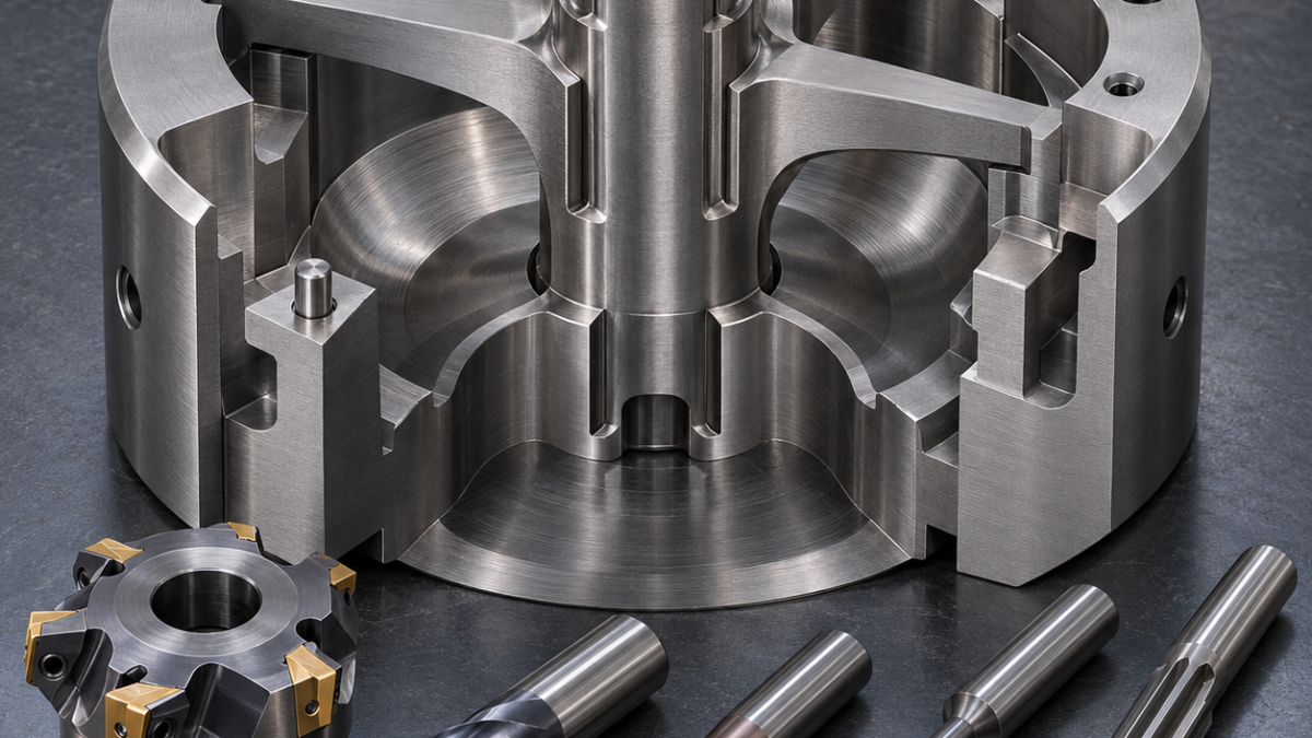
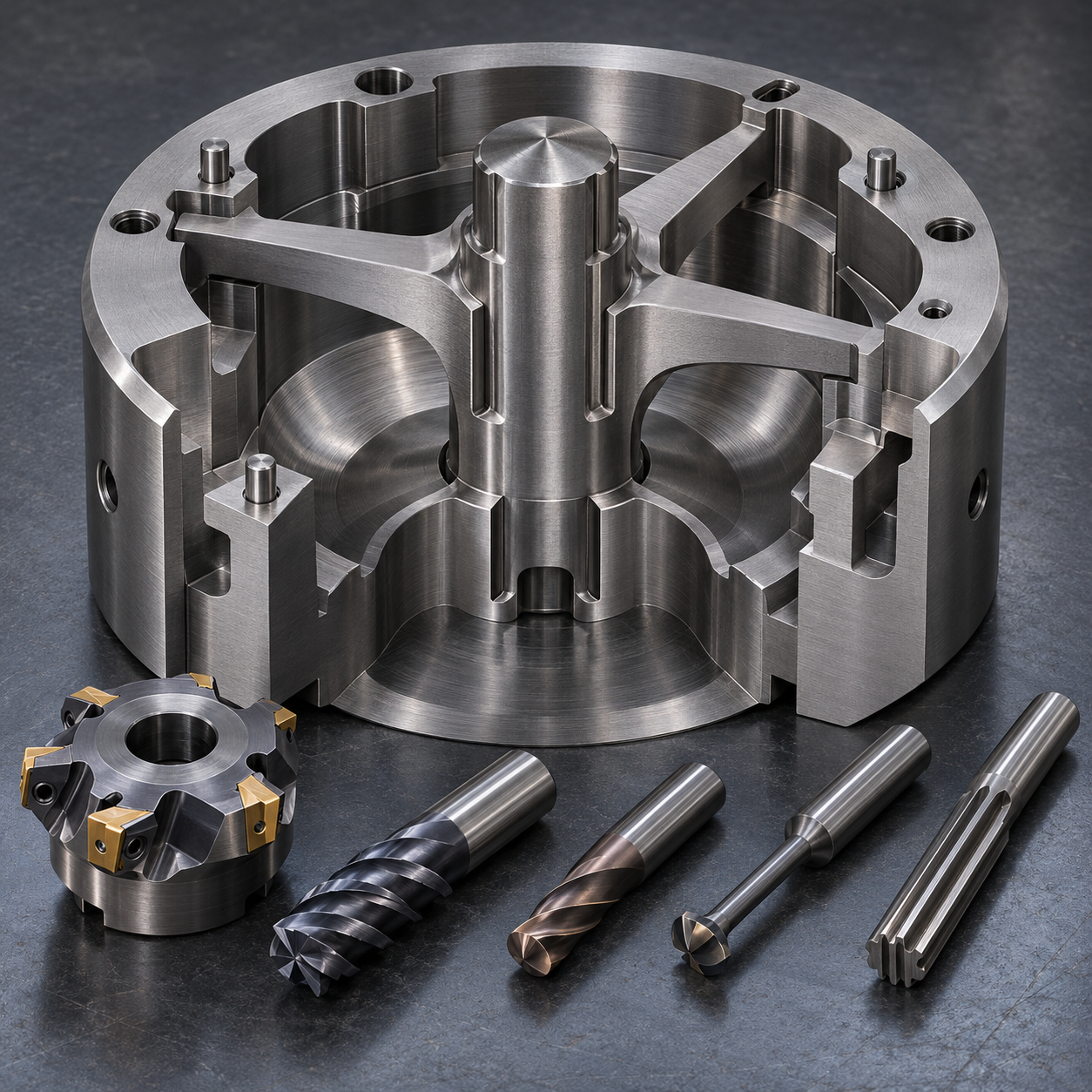
English: H11 Extrusion Die Mandrel Tooling for Bridge Undercuts and Bearing Lands
This hypothetical drawing asks how to machine an H11 extrusion porthole die mandrel when the bearing land must remain true to the dowel datum after the bridge pockets, heat treatment and nitriding sequence. The answer is to separate bulk removal, bridge-underface access and final land correction instead of forcing one long-reach cutter to do every feature.
Read the drawing as a load-and-stock chain
The 210 mm mandrel is located by a ground back face and two 10 H7 dowel bores. Three bridges feed a central mandrel, while their undersides form the welding chamber. The hypothetical requirements are 0.02 mm land profile, 0.015 mm dowel-to-land position and Ra 0.4 micrometre on the bearing surface. Leave 0.30 mm on the land before 46–48 HRC heat treatment, but only 0.12 mm on broad chamber blends so quench scale can be removed without thinning a bridge.
Feature-to-tool decisions for the H11 mandrel
| Drawing feature | Specified tool, geometry and holder | Why it fits / rejected alternative |
|---|---|---|
| Back face and portholes | 50 mm fine-pitch face mill; 12 mm 5-flute AlTiN radius end mill | Positive geometry limits stress; a coarse shell mill can deflect the bridge plate. |
| Bridge undercuts | 8 mm 4-flute AlCrN lollipop cutter, minimum relieved neck, shrink-fit | Reaches under the bridge; a long straight end mill bends and leaves unequal walls. |
| Bridge-root blends | 6 mm toroidal carbide mill, 4 flutes, tilted axis | Controls the specified fillet; manual blending cannot preserve profile traceability. |
| Dowel bores | Carbide drill, helical interpolation and fine boring/reaming after datum recovery | Corrects position and size; a reamer alone follows a displaced pilot. |
| Hardened bearing land | 4 mm 4-flute submicron carbide, TiSiN, short shrink-fit reach | Survives 46–48 HRC intermittent finishing; ceramic is too brittle at interrupted entries. |
| Edge break | 90-degree fine-grain carbide chamfer mill | Creates measurable chamfers; uncontrolled hand stones can round the bearing edge. |
Rough while the bridges can still carry cutting load
Face the annealed blank with a 50 mm fine-pitch cutter using positive PVD-coated carbide inserts with a light edge hone. Open each porthole using a 12 mm five-flute variable-helix AlTiN end mill, 0.5 mm corner radius and shrink-fit holder. An adaptive path keeps radial engagement constant and evacuates chips toward the open side. Alternate the three pockets by depth so residual stress is released symmetrically; plunging one pocket to full depth first would twist the mandrel.
Reach the welding chamber without borrowing stiffness
A relieved 8 mm four-flute AlCrN lollipop cutter reaches beneath each bridge from two indexed orientations. Its reduced neck is limited to the drawing-required reach, and the CAM model includes holder, neck and bridge collision envelopes. A generic long-reach end mill is rejected because shaft bending changes chamber thickness. Blend the bridge root with a 6 mm toroidal carbide mill, using a tilted tool axis and small axial steps so the fillet is generated by the insert radius rather than by hand polishing.
Finish the bearing land after thermal movement
After heat treatment, verify the back face and dowels before removing land stock. A 4 mm four-flute submicron carbide end mill with TiSiN coating, 0.02 mm edge hone and short shrink-fit projection takes a semifinish pass, then a separate fresh tool makes the final climb pass with about 0.05 mm radial stock. Ceramic is rejected because the land contains interrupted entries; wire EDM is reserved only for inaccessible relief and is kept away from the functional land to avoid an unqualified recast layer.
Control burrs, tool life and inspection by feature
Deburr nonfunctional edges with a 90-degree carbide chamfer mill before nitriding, protecting the sharp bearing transition specified on the drawing. Stop roughing tools when spindle load or corner-radius wear trends upward; stop the land tool when profile drift, edge microchipping or finish changes. CMM checks dowel-to-land relation and bridge thickness, a form tracer checks the bearing profile, and white-light measurement checks Ra. Fluorescent magnetic-particle inspection follows heat treatment where the material specification requires it.
Related technical comparisons: H13 hot-runner nozzle tooling; M42 cutter-blank stock planning.
Practical FAQ
Why not finish the bearing land before heat treatment? The bridge geometry and thermal cycle can move the land relative to the dowels, so correction stock must remain.
When is EDM a sensible alternative? Only for a genuinely inaccessible relief after its recast layer and dimensional effect have been qualified; it is not the default for the bearing land.
Which holder is safest below a bridge? A collision-checked shrink-fit or high-precision hydraulic system with only the required reach, verified for runout before the lollipop tool enters.


