English: FR4 CNC Tool Selection for Castellated Edges, Micro Via Holes and Counterbores
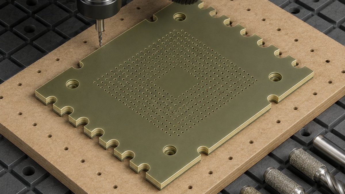
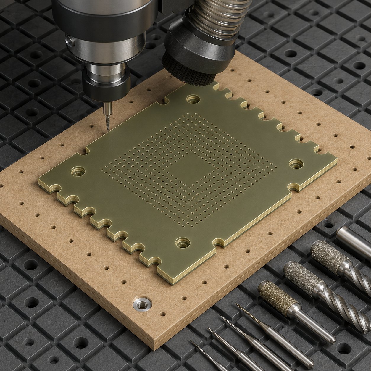
For an FR4 test-socket adapter plate, the cleanest castellated edge is normally made by drilling the full hole while the laminate is supported, then profiling through its centerline. The same drawing may combine 0.25–0.45 mm micro via holes, shallow counterbores, a positional hole array and fragile half-holes at the perimeter. Tool choice must control glass-fiber abrasion, resin heat, entry lift and exit breakout together; a general-purpose metal-cutting recipe cannot do that.
Translate the drawing into laminate risks
Treat the board face, two tooling holes and one finished datum edge as the locating system. Record laminate thickness, copper presence, finished hole diameter, position tolerance and the permissible glass-fiber halo. A hypothetical 1.6 mm plate with Ø0.30 mm vias has an effective depth near 5.3×D; its risk is chip packing and exit breakout. A Ø1.0 mm castellated hole later cut in half has a different risk: the profile cutter can pull unsupported fibers out of the plated or unplated wall.
Feature-to-tool map for FR4
| Drawing feature | Tool, geometry and holder | Selection logic / rejected alternative |
|---|---|---|
| Tooling holes and datum pair | Solid-carbide drill plus carbide reamer only if pilot position is proven; short precision collet | Establishes repeatable registration; a reamer cannot correct a displaced pilot. |
| Ø0.25–0.45 mm micro via array | 130–140° micrograin carbide, 2 flutes, diamond-coated or qualified ultra-sharp uncoated, minimum projection | Diamond resists glass abrasion; a dull general-purpose drill heats resin and lifts fibers. |
| Shallow counterbore around a micro hole | 1.5–2.0 mm diamond-coated 2-flute router in shrink-fit/precision collet, helical entry | Large flute space clears dust; a 4-flute metal mill packs debris and rubs the laminate. |
| Full holes for future castellations | Short diamond-coated carbide drill with entry sheet and backup plate | Full support protects the wall; drilling after profiling starts on a half surface and splinters the edge. |
| Perimeter and castellated release | 2–3 mm diamond-cut or compression router, 2 flutes, vacuum shoe, climb-finish pass | Balanced top/bottom cutting limits ply lift; hand filing pulls glass bundles. |
| Small edge break | Fine diamond abrasive brush or qualified controlled micro-chamfer, minimal pressure | Removes loose whiskers without bell-mouthing holes; aggressive manual scraping changes land width. |
Drill the supported hole array before profiling
Clamp the panel between a clean phenolic entry sheet and a replaceable high-density fiber or aluminum backup. Drill the datum holes and micro-hole array before any perimeter release. Use a 130–140° two-flute micrograin carbide drill with diamond coating when the glass content and batch length justify it; for a very short trial, an uncoated ultra-sharp carbide drill may give a cleaner first hole but wears faster. Minimum projection and a precision collet keep runout from consuming the diameter allowance.
Create counterbores without lifting the top ply
For shallow counterbores, interpolate with a 1.5–2.0 mm diamond-coated two-flute router or use a piloted carbide counterbore when concentricity to the micro hole dominates. Enter with a shallow helical path and leave 0.03–0.05 mm for a light circular finish. A conventional four-flute metal end mill is rejected because its small flute space traps abrasive dust and its honed edge can lift the top glass ply.
Release castellations with controlled radial force
Machine castellations as full supported holes, inspect them, then rough the outline with a 2–3 mm diamond-cut or compression router. Leave 0.10 mm radially and finish the perimeter in a single climb-milling pass with vacuum extraction placed behind the cutter. The centerline of each full hole must match the finished outline; compensating a misplaced profile later changes the remaining half-hole width. Do not hand-file the edge because it rounds the land and pulls individual glass bundles.
Dust, tool life and inspection
Use filtered local extraction rather than blowing dust through spindle bearings or across the inspection surface. Track life by hole-count family, thrust or spindle-load trend, entry halo, exit whiskers and diameter—not by waiting for breakage. Optical inspection measures fiber pullout, counterbore lip and castellated land width; calibrated pins confirm accessible holes, while a vision system checks the array relative to tooling datums. Stop when two consecutive locations trend toward the diameter limit or the glass halo exceeds the drawing note.
Related tooling decisions
Use the micro-hole drilling and burr-control decision guide to choose runout, exit support and inspection by hole geometry. Compare FR4 dust and delamination with the abrasive breakout logic in the 96% alumina nozzle plate, and with heat-sensitive polymer finishing in the Torlon labyrinth-seal case.
FR4 tooling FAQ
Should FR4 micro drills be pecked? Only when the validated cycle actually evacuates dust; unnecessary re-entry can rub resin and enlarge the entry. Is diamond coating always better? It improves abrasive life, but edge thickness may hurt the smallest holes, so tool diameter and coating specification must be qualified together. Why drill castellations before profiling? The surrounding laminate supports the hole wall and makes the later half-hole predictable. Can compressed air replace extraction? It redistributes hazardous glass/resin dust and may contaminate guides; capture at source is preferred.


