
English: 42CrMo4 Servo Piston Tooling for Metering Lands and Damping Holes
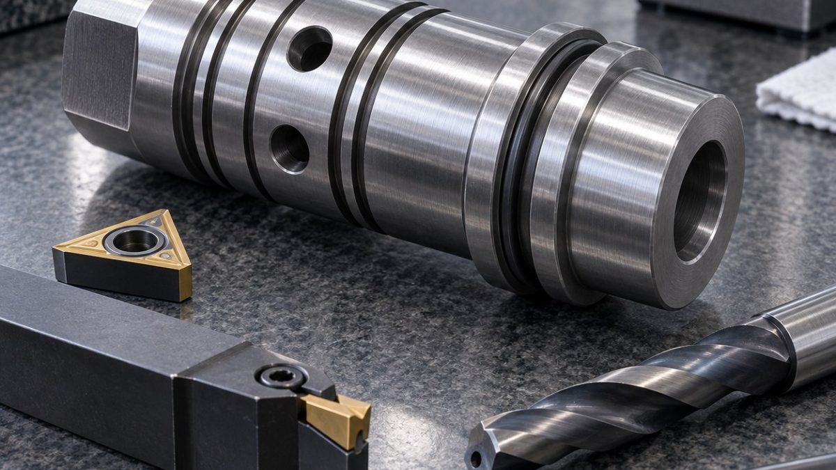
The drawing is controlled by the common axis of several narrow metering lands and their angular relationship to cross damping holes. The hypothetical centerline is datum A, an end face is B and a wrench flat clocks the holes. Heat-treatment stock must be assigned before finish-tool selection.
Read functional datums before selecting tools
| Drawing feature | Carbide tool and holder | Why selected / alternative rejected |
|---|---|---|
| Blind axial bore | Coolant-through carbide drill then short anti-vibration boring bar with PVD steel-grade insert | Boring corrects drift; a long end mill cannot hold deep straightness. |
| Metering lands rough/semifinish | Positive CVD-coated carbide turning insert, 0.4 mm radius, rigid holder | Stable roughing leaves equal grind/finish stock; grooving each land independently creates steps. |
| Metering land finish | PVD cermet or fine-grain carbide wiper insert, light continuous pass | Low force and consistent texture; repeated spring passes rub hardened steel. |
| Cross damping holes | 2 mm through-coolant carbide drill from spot-faced pads, precision collet | Normal entry controls walk; direct drilling on a diameter deflects. |
| Seal undercut and flats | 1.5 mm PVD carbide groover plus 6 mm 5-flute AlTiN end mill | Dedicated groove width controls corner; hand-ground flats lose clocking. |
Match each drawing feature to a cutter
Turn the datum center and rough bore before stress relief or heat treatment specified by the hypothetical route. Re-establish centers, semifinish all lands in one tool path and mill wrench flats. Spot-face and drill opposing damping holes before the final land pass so internal burrs can be back-chamfered. Finish the seal undercut and lands from the same axial setup.
Control material-specific failure modes
42CrMo4 changes cutting response after heat treatment and can produce notch wear at land shoulders. Confirm hardness before choosing the finishing grade, maintain feed across shoulders and monitor chip color. A repeated diameter drift on every land points to thermal or center error, not six independent offsets.
Verify the released part
Measure all land diameters and axial spacing from common datum centers, then inspect cylindricity and surface texture. Borescope the blind bore and cross-hole intersections and verify the seal-groove corner radius. Hydraulic leakage, dynamic response and fatigue require separate system tests.
Practical tooling FAQ
Why drill damping holes before final land turning?
The final turning pass removes any raised exit material after controlled back-chamfering.
Why not offset every land separately?
A common shift usually comes from center, temperature or tool condition; independent offsets can destroy the designed relationship.
spool sleeve bore and window tooling · hardened alloy groove and hole tooling