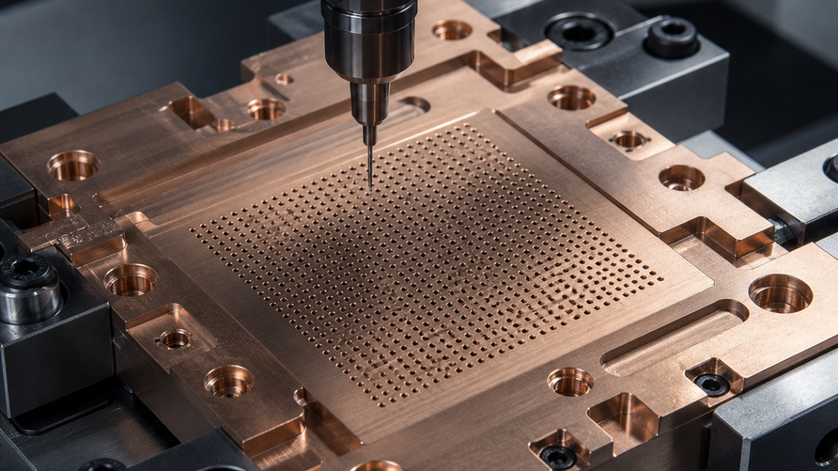
English: C17200 Probe-Card Guide Plate CNC Tool Selection for 0.18 mm Hole Array
For a C17200 probe-card guide plate, the search intent is practical: select tools that can hold a Ø0.18 mm hole array on pitch without smearing the exits or warping the 2.2 mm plate. The workable answer is a short polished microdrill in an ultra-low-runout holder, a separate shallow entry-form tool, and a bonded carrier that stays attached through the last hole. This hypothetical case treats drilling order, heat, and tool-change limits as drawing decisions rather than afterthoughts.
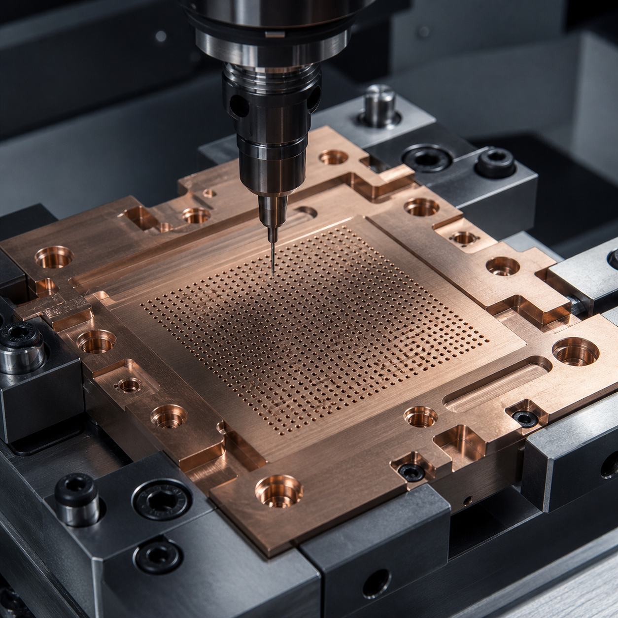
Reading the array as an error map
Datum A is the lapped lower face; ground rails B and C establish rotation. The active field contains 420 through holes at 0.50 mm pitch. Each is Ø0.180 +0.006/0 mm with a Ø0.32 × 0.08 mm entry relief, true position Ø0.012 mm to A|B|C, and a minimum 0.31 mm land between adjacent entries. Overall thickness is 2.20 ±0.015 mm, A flatness is 0.020 mm free state, and neither a rolled exit burr nor copper smeared into the bore is acceptable.
Age-hardened C17200 combines higher strength than free-cutting copper with adhesive chip behaviour. The plan therefore separates face cutting, array location, entry relief, and release. Any production route also needs a documented exposure assessment and appropriate capture of beryllium-containing chips and mist; this article does not replace site-specific industrial-hygiene controls.
Feature-to-tool selection by error source
| Drawing feature | Specified carbide tool and holder | Decision and rejected alternative |
|---|---|---|
| A face and carrier pads | Ø6 three-flute uncoated micrograin carbide, polished 38° helix, R0.10, 5 µm edge hone, short hydraulic chuck | The sharp polished edge limits built-up material. A thick general-purpose TiAlN coating is rejected because its rounded edge tends to rub this copper alloy. |
| B-C locating rails | Ø2 four-flute ZrN-coated carbide end mill, 35° variable pitch, 4 mm reach, shrink-fit holder | ZrN reduces adhesion while four flutes stabilize the finishing cut; the reach is kept only as long as the rail requires. |
| Ø0.18 through-hole array | Ø0.18 two-flute polished carbide microdrill, 130° split point, 0.45 mm flute length, minimal edge prep, precision shrink collet with runout verified at the point | A 0.30 mm flute length is too short for breakthrough; a longer 1.0 mm drill loses column stiffness. Laser drilling is not substituted because the drawing controls a mechanically finished bore and exit condition. |
| Ø0.32 entry relief | Ø0.30 two-flute uncoated carbide drill mill, 120° included point, programmed 0.08 mm depth, ultra-precision collet | A combined step drill would enlarge the entry every time microdrill wear changes; separating the relief preserves the Ø0.18 tool’s short geometry. |
| Two Ø2 H6 datum bores | Ø1.85 coolant-fed carbide drill followed by Ø2 six-flute cermet-compatible carbide reamer, left-hand slow spiral, 4 µm hone | The reamer follows a stable pilot and produces size; interpolation with the Ø2 mill is rejected because tool runout would print directly into the datum. |
| M2 mounting threads | Ø1.60 polished carbide drill then Ø1.25 three-flute ZrN carbide thread mill, single-form profile, hydraulic holder | Thread milling keeps a broken tool recoverable and permits pitch-diameter compensation; a roll tap would impose unwanted forming load on the thin plate. |
| Perimeter and 0.05 mm edge break | Ø3 three-flute ZrN end mill for contour; Ø2 four-flute 90° polished carbide chamfer mill | The controlled chamfer is cut before release. Hand brushing is rejected because it can drag metal over the micro-hole mouths. |
Drilling sequence, carrier and tool-life gate
The blank is stress-relieved, both broad faces are skimmed with 0.04 mm stock remaining, and the lower face is bonded to a ground ceramic carrier beyond the finished outline. A and the datum rails are finished first. The array is divided into twenty-one 20-hole cells; machining alternates diagonally between cells so local temperature and clamp load do not accumulate in one corner. Each microdrill entry is single-feed after a short dwell-free approach, with through-exit support from a replaceable backing foil.
Runout is measured at the drill point and capped at 0.0015 mm for this route. Holes 1, 20 and 21 form an initial capability gate: optical position, pin acceptance, exit image and spindle-load signature must agree before the remaining cells run. A rise in load, a continuous feather at the exit, or more than two consecutive oversize relief images retires the drill. Clean low-viscosity fluid and point extraction remove chips; recutting loose copper is not accepted.
Free-state inspection and practical FAQ
While bonded, a vision CMM verifies B-C and the entry-centre map; calibrated optical pin methods and a qualified air-flow correlation sample the Ø0.18 bores. White-light measurement checks entry depth and land width. After controlled debonding and cleaning, the plate rests for thermal equalization before A flatness, thickness, and selected true positions are repeated. This separates machining accuracy from carrier restraint.
Which tool is best for drilling 0.18 mm holes in C17200?
A stub, polished two-flute carbide microdrill with a thinned 130° point and point-level runout verification is preferred; the qualified flute length should only exceed plate thickness and backing penetration.
Why not use one step drill for the hole and entry relief?
Separate tools keep the fragile Ø0.18 drill short and allow relief depth to be corrected without changing the guide bore.
How is burr control verified across hundreds of holes?
The process uses mapped inspection cells, exit images and load trends rather than relying on an end-of-batch visual sample.
Related guidance: micro-tool breakage prevention and carbide-holder runout control.


