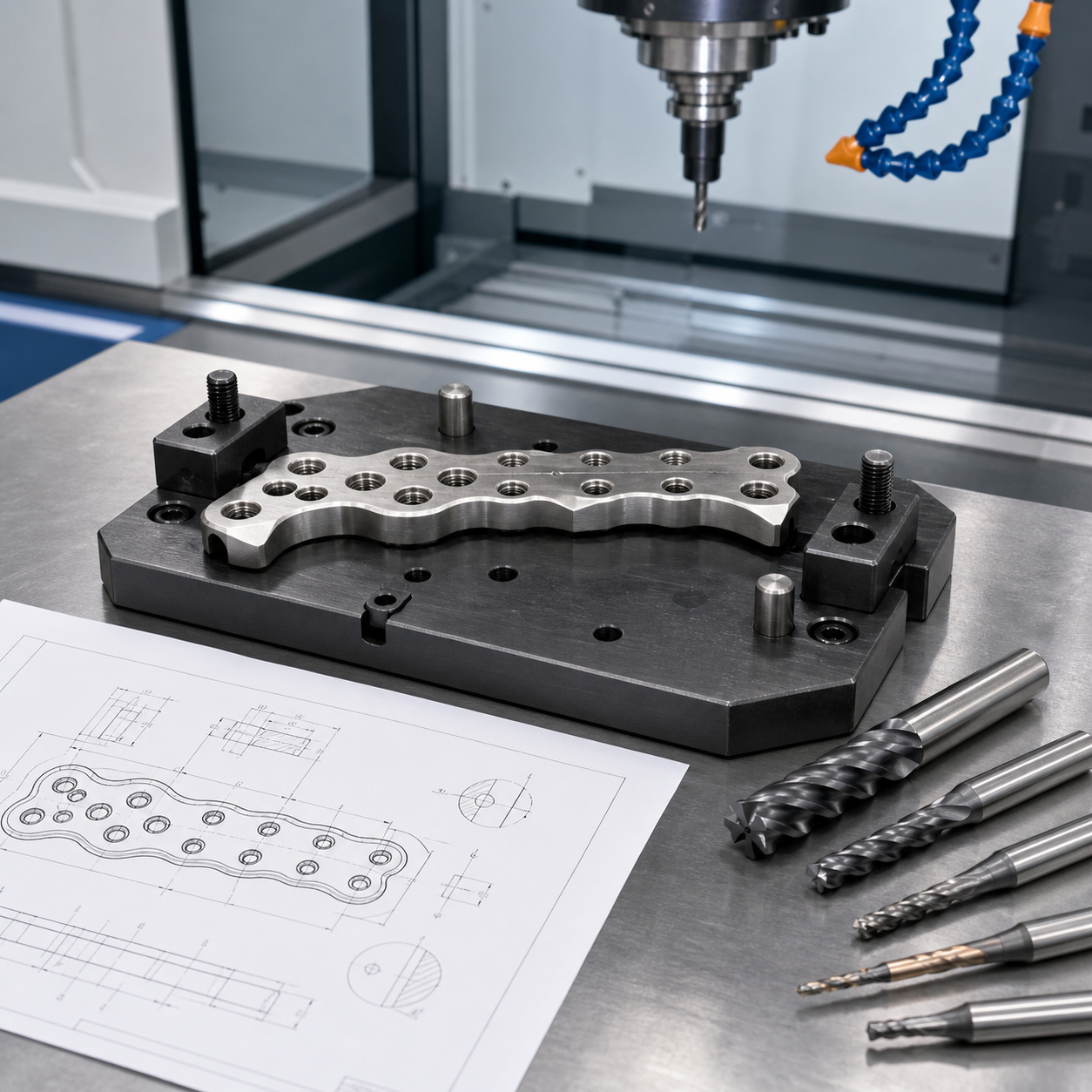
English: Ti-6Al-4V Bone Plate Tooling for Locking Holes and Burr Control
The upgrade answers how to machine locking holes in a thin Ti-6Al-4V plate without lifting the curved profile or leaving a patient-facing burr. Hole axis, countersink form, plate thickness and free-state contour are treated as one tolerance chain.
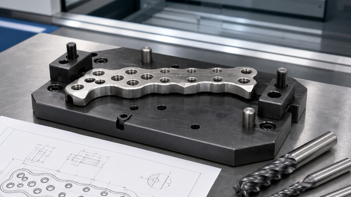
This CNC machining case studies a Ti-6Al-4V orthopedic bone plate with a curved outside profile, multiple countersunk screw holes, elongated slots and a final thickness of about 3.2 mm. The example drawing calls for 0.05 mm hole true position, smooth edge transitions, controlled countersink depth and a burr-free surface condition on every patient-contact edge. The exact medical requirements must always come from the approved customer drawing and quality plan; this article focuses on process planning and tool selection.
The machining challenge is not only titanium heat. A thin bone plate can lift from the fixture, chatter during contour finishing and create difficult secondary burrs around angled holes. The process must keep cutting edges sharp, support the part near every functional feature and avoid rubbing that hardens the surface before the final pass.
Fixture and Datum Plan
Start with oversize plate stock and create two protected locating holes plus a flat support face. The second setup should use a low-profile fixture with hardened locating pins, vacuum or distributed mechanical support, and small relief pockets beneath through holes. Clamping should avoid the final contour so the cutter can complete the outside profile without leaving witness marks.
For curved plates, a soft nest that follows the underside geometry reduces local bending. If the blank is flat and the final plate is later formed, machine the hole pattern before final contouring and leave enough tabs or sacrificial stock to maintain stiffness until the last operation.
Tool Selection
| Feature | Suggested tool | Reason |
|---|---|---|
| Rough contour | 4-flute variable-helix carbide end mill, AlTiN or similar coating | Stable engagement and heat resistance in titanium |
| Finish contour | Sharp 5-flute carbide end mill with small corner radius | Clean wall finish with lower edge chipping risk |
| Screw holes | Carbide drill followed by interpolation or reaming when required | Controls position, diameter and surface quality |
| Countersinks | Dedicated carbide countersink with controlled dwell-free feed | Maintains seat angle and reduces chatter rings |
| Edge break | Small ball end mill or programmed chamfer mill | Produces repeatable, inspection-friendly edges |
Starting Cutting Parameters
For a 6 mm carbide end mill in Ti-6Al-4V, a practical trial range is 45-70 m/min cutting speed, 0.025-0.055 mm feed per tooth and light radial engagement with strong coolant. Hole drilling may start near 35-55 m/min with pecking only when chip evacuation requires it. Countersinking should use positive feed, no dwell and a toolpath that enters cleanly without rubbing at the seat.
These are commissioning ranges, not universal settings. Final values depend on tool grade, holder runout, coolant pressure, machine rigidity and the heat-treatment condition of the material.
Process Sequence and Inspection
- Verify material certificate, blank thickness and grain direction requirements.
- Machine datum holes and support face while stock is still rigid.
- Rough holes and contour, leaving small stock on functional edges.
- Finish critical screw holes and countersinks before the outside profile becomes too flexible.
- Finish the contour with constant engagement and low radial force.
- Deburr under magnification using a controlled process, not aggressive hand scraping.
- Inspect hole position, countersink depth, edge radius, surface finish and final thickness.
For SEO and shop-floor usefulness, the important search theme is specific: Ti-6Al-4V bone plate CNC machining with fixture support, carbide tool selection and burr control. The article avoids pretending that one speed chart fits every medical part; traceability and validated inspection remain essential.
Locking-hole feature-to-tool checkpoint
Support the preformed underside on three inspected datum pads with a replaceable polymer nest. Rough the outline with a 6 mm four-flute AlTiN radius end mill at constant engagement; interpolate locking holes with a 4 mm three-flute variable-helix carbide tool, then finish the thread or locking form with the drawing-qualified cutter. A drill-plus-countersink stack is rejected when it cannot correct axis position after springback.
| Drawing checkpoint | Tool / method | Acceptance logic |
|---|---|---|
| Curved support | Three datum pads plus polymer nest | No lift or imprint |
| Locking hole | 4 mm 3-flute interpolation plus qualified form tool | Axis, roundness and form |
| Patient-side edge | 1 mm reverse chamfer tool | Burr height and surface integrity |
Inspection and stop rules
Alternate holes across the plate to balance heat. Use a 1 mm back-chamfer tool from the supported side and prohibit freehand blending on the patient face. Measure hole axis and form by CMM or optical probe, inspect burr height at magnification, then release and recheck free-state contour on minimal supports.
Related tooling paths: titanium bracket heat-control plan; angled titanium guide tooling.
Focused FAQ
Why interpolate before form finishing? It corrects location and roundness. Why a polymer nest? It distributes load without imprinting the curved surface. Tool-life limit? Burr growth, thrust drift or hole-form deviation.
For the drill, holder, exit-support and burr-control decision behind this feature, use the Micro-hole decision hub.