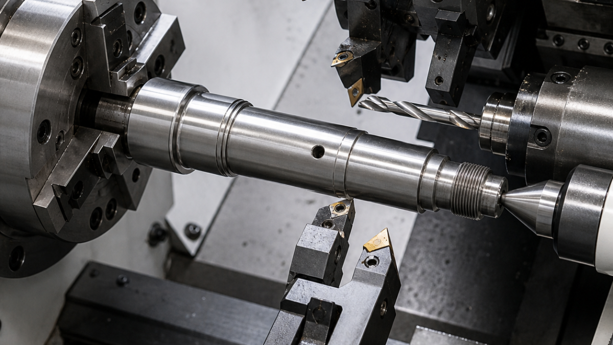
English: Ti-5553 Landing Gear Axle CNC Tooling Case: Bearing Journals and Cross-Hole Breakout
The tooling answer for a Ti-5553 landing-gear axle is a controlled turn–drill handoff: a tough coated insert removes the forged skin, a fresh positive finishing insert establishes both bearing journals from one axis, a guided carbide drill creates the deep lubrication passage, and a back-chamfer tool removes the cross-hole feather without touching the finished journal. This hypothetical drawing case explains why those tools are separated instead of asking one general-purpose insert to do everything.
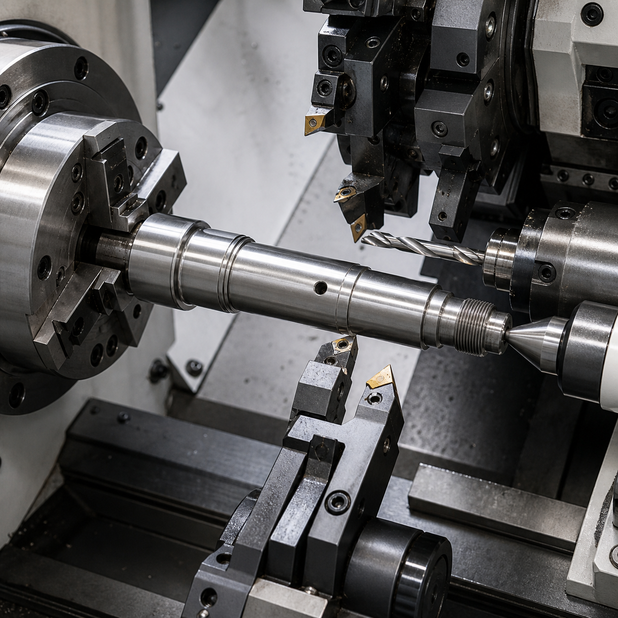
Tolerance flow from the axle axis
Journal J1 is datum A; the left shoulder is datum B and the Ø6 lubrication breakout clocks datum C. J1 is Ø68 k5, J2 is Ø62 k5, their common-axis total runout is 0.012 mm, and the 1:12 tapered seat is limited to 0.015 mm runout from A. Two 2.5 mm relief grooves protect bearing corners, the axial oil bore is Ø10 × 185 mm, and the M48 × 1.5 thread must gauge without rolling a burr toward J2. Journal finish is Ra 0.4 µm. The forging may carry local alpha-case and uneven scale, so skin removal and precision finishing use different edge preparations.
Drawing feature to carbide tool map
| Feature | Selected tool, geometry and holder | Decision and rejected alternative |
|---|---|---|
| Forged skin and stock balance | CNMG 120408, tough S-grade micrograin carbide, PVD TiAlN, 0.05 mm edge hone, rigid lever-lock holder with high-pressure coolant | The reinforced edge survives scale interruptions. A polished uncoated finishing insert is too fragile for the first contact. |
| J1/J2 bearing journals | Ground VBMT 160404 positive insert, fine-grain carbide with thin PVD coating, sharp rake, R0.4, precision modular holder | Low radial force and controlled nose radius support Ra 0.4. A wiper geometry is rejected because small alignment error can widen the contact band. |
| 1:12 tapered seat | Fresh copy of the VBMT finishing edge, calibrated tool station, minimum overhang | One edge family keeps size and surface response consistent. A form tool would load the taper across its full width. |
| 2.5 mm relief grooves | 2.0 mm PVD-carbide grooving insert followed by two compensated side shifts, through-tool coolant | Side shifts control both corners and avoid a fragile 2.5 mm form blade rubbing the titanium. |
| Ø10 × 185 mm oil bore | Single-lip solid-carbide gun drill, 30×D qualified length, TiAlN tip, guide bush and filtered high-pressure oil | The guide bush controls drift. A standard twist drill at this depth would wander and recut chips. |
| Ø6 cross passage | Ø5.8 stub carbide drill, 140° point, four-margin geometry, hydraulic chuck; Ø3 reverse-cut carbide back-chamfer tool | The drill controls breakout, then the reverse cutter removes the internal feather. Hand scraping through the bore is not repeatable. |
| M48 × 1.5 thread | Full-profile PVD-carbide threading insert, sharp positive chip former, rigid external holder | Controls crest and root in few passes. A partial-profile insert leaves crest burr dependent on blank diameter. |
Machining sequence, support and heat control
The forging is first probed at both journal envelopes, then rough-turned between a chuck and live center while a programmable steady supports the center span. Equal stock is left on J1 and J2, and the component rests before a second center reference is cut. In the finishing setup, J1, J2 and the taper are completed without releasing the axial stop. The final journal pass uses constant surface speed, no dwell and a documented insert edge; a spring pass is permitted only after an air-gauge trend proves it cuts rather than rubs.
The gun drill enters from B through a prepared pilot. Flow, pressure and chip signature are monitored before the tool reaches the cross-hole zone. C-axis drilling of Ø6 occurs while a sacrificial support pin occupies the axial passage; the reverse chamfer then cuts only the internal edge. Titanium’s low thermal conductivity makes flank wear, notch wear at shoulders and blue compacted chips the principal tool-life signals. A rising load slope triggers replacement—feed is not reduced until the edge begins polishing.
Inspection and practical search questions
A roundness instrument measures J1 and J2 at three axial stations and reconstructs their common axis. Air gauges verify k5 sizes after temperature equalization; a CMM checks the taper, shoulders, groove location and cross-hole clocking. Borescope inspection confirms a continuous internal break with no loose feather. Oil-flow testing supplements, but does not replace, the measured bore path. Thread acceptance uses a clean ring gauge after the journal surfaces are protected.
Which carbide insert should finish Ti-5553 bearing journals?
Use a ground positive fine-grain insert with a sharp rake, small nose radius and stable PVD coating; here VBMT R0.4 limits radial force while holding Ra 0.4 µm.
How is the burr removed where a cross hole meets a deep oil bore?
Support the breakout during drilling, then use a small reverse-cut carbide back-chamfer tool viewed through a borescope.
Why not use a conventional twist drill for the 185 mm oil passage?
A guided single-lip carbide drill provides controlled straightness and continuous high-pressure chip evacuation at this depth.
Compare the thermal-cutting choices in Ti-6Al-4V thin-section machining and the axis-to-hole handoff in a pressure-probe tooling case.


