English: Macor Vacuum Feedthrough Insulator CNC Tooling Case: Thin Flange and Threaded Holes
Macor tooling should be selected by the failure it must prevent. Powder at a hole exit points to unsupported drilling, crescent chips at the flange point to excess radial force, and torn ceramic threads point to a tap wedging in a blind hole. For this hypothetical vacuum-feedthrough insulator, PCD defines the concentric seal geometry, stub carbide drills create supported pilots, and a single-row carbide thread mill avoids tap torque.
Functional geometry and permissible edge condition
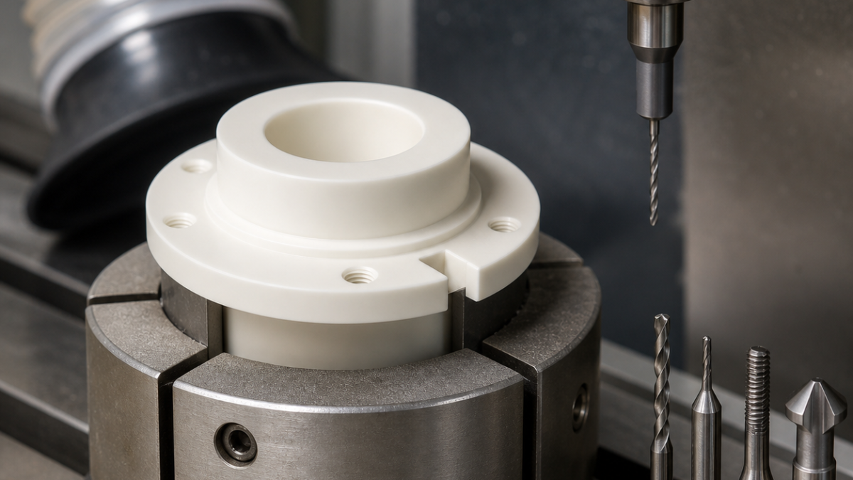
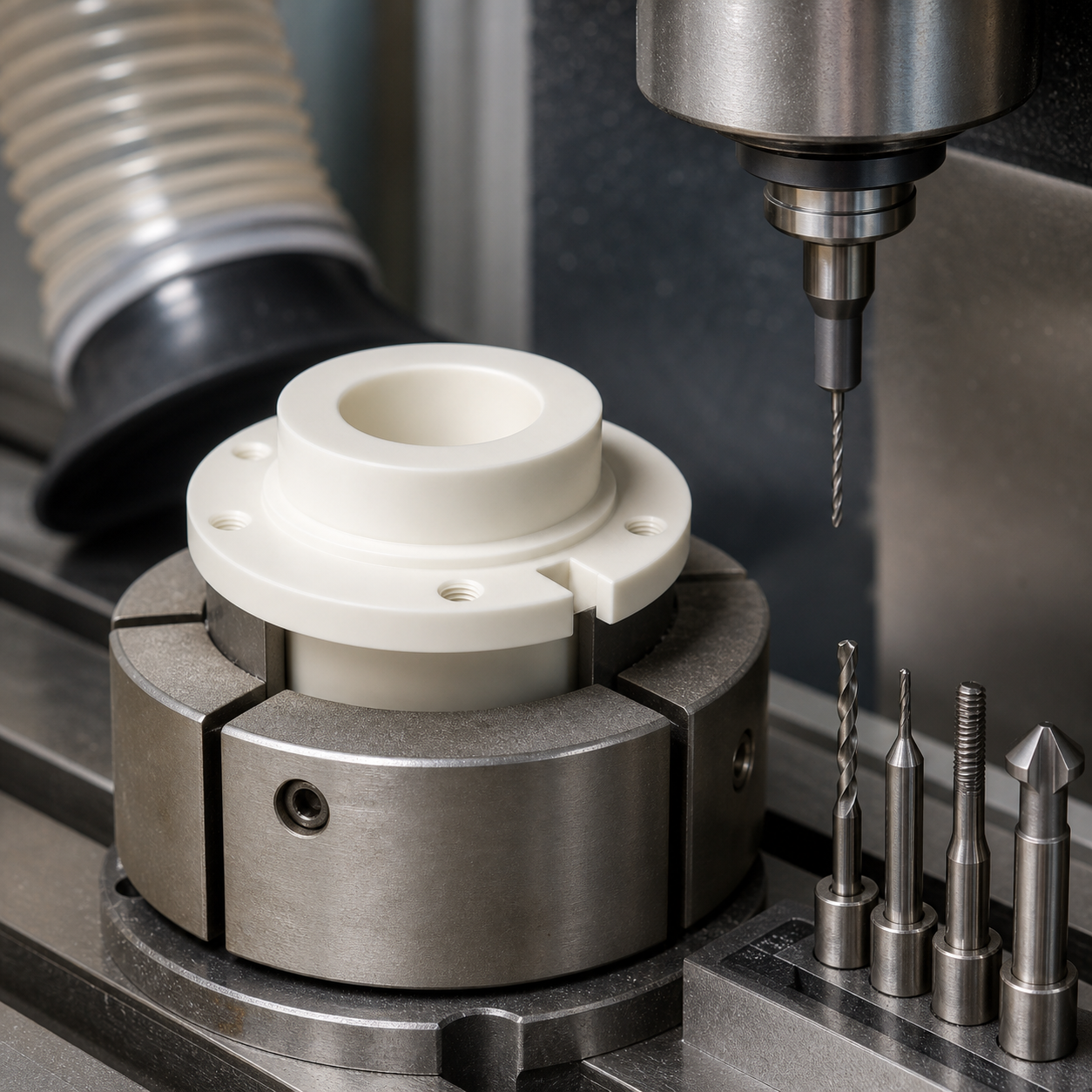
Seal shoulder A is the primary datum, central bore B establishes the conductor axis, and anti-rotation slot C clocks four M3 holes. The Ø24 bore is H8, A-to-B concentricity is 0.035 mm, the 2.6 mm flange is flat within 0.030 mm, and the shoulder finish is Ra 1.6 µm. All vacuum-side edges require a 0.15 ±0.05 mm chamfer; a visually tiny uncontrolled chip outside that band is unacceptable because it can create a leak path or assembly stress point.
Tool trial matrix: feature, signature and final selection
| Drawing operation | Selected tool and holder | Rejected trial / failure signature |
|---|---|---|
| Seal face and outside diameter | PCD-tipped positive turning tool, R0.2 nose, polished rake, rigid miniature boring-bar holder | General-purpose honed carbide produced radial crushing and a chalky edge at the flange. |
| Ø24 H8 central bore | Ø12 two-flute diamond-coated carbide end mill, short flute, helical interpolation in a shrink holder | A full-diameter drill created an exit ring chip; interpolation keeps force tangent and leaves correction stock. |
| 2.6 mm flange contour | Ø6 two-flute diamond-coated fine-grain carbide, 20° low-helix geometry, 8 mm flute, hydraulic micro chuck | A high-helix four-flute cutter lifted the unsupported flange and produced crescent breakouts. |
| M3 blind-hole pilots | Ø2.5 stub solid-carbide drill, 130° point, double-margin, 6 mm flute, precision collet | A long jobber drill flexed and peck impacts marked the hole mouth. |
| M3 internal threads | Ø1.9 single-row micrograin-carbide thread mill, uncoated sharp edge, hydraulic micro chuck | A forming tap is rejected outright; a cutting tap also wedges chips and applies burst torque to the ceramic. |
| 3 mm anti-rotation slot | Ø2.5 two-flute diamond-coated carbide, straight flute, 4 mm cutting length | A long spiral tool pulled a chip from the slot exit. |
| Vacuum-side chamfers | Ø6 PCD 90° two-edge chamfer tool, preset axial height | Hand stoning varied the edge break and obscured small cracks. |
How the fixture makes brittle machining possible
A ground polymer split collet supports the cylindrical land over nearly 300°, while a replaceable PEEK washer sits directly beneath the flange. Clamping torque is recorded; the collet is never tightened by visual feel. The seal face is cut first, the bore is interpolated from both ends with 0.10 mm overlap away from the functional shoulder, and the flange contour is finished in shallow axial levels toward the support. Blind holes use a smooth feed with full withdrawal for vacuum extraction rather than impact pecking.
Machining is dry under source extraction qualified for fine ceramic dust; compressed-air blasting across the operator or guideways is prohibited. Edge-chip growth, spindle-load spikes and a change from granular to plate-like debris are tool-change signals. The thread mill makes a rough orbit and a compensated finish orbit, then exits along the bore center. No metal screw is used as an in-process gauge while the part is clamped.
Inspection without creating the defect being measured
A low-force optical system measures the flange edge, chamfer width, slot exit and hole mouths before contact inspection. The CMM uses a small calibrated force to build A-B-C and checks the bore at two depths. Threads are evaluated optically and with a polymer master at limited torque; a metal GO plug is reserved for the approved final method. Flatness is measured on three compliant supports, and the finished assembly receives the specified helium-leak test only after cleaning.
What tool should machine Macor blind threads?
A small single-row carbide thread mill avoids tap wedging and permits separate rough and finish diameter compensation.
How can a thin Macor flange be machined without edge chipping?
Support it immediately underneath, use a low-helix two-flute diamond-coated cutter, shallow axial levels and a toolpath directed toward the support.
Should Macor dust be blown away with shop air?
No. Capture it at source with the facility’s qualified extraction and cleaning process; uncontrolled air spreads abrasive fine dust.
For contrast, see post-sinter alumina edge control and dry dust management around fragile features.