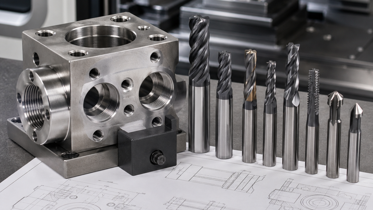
English: Stainless Steel Valve Body Machining Tools for Bores, Seats and Ports
Read the flow path before choosing a cutter
For a stainless steel valve body, the useful search answer is not a generic list of end mills. The drawing must be reduced to one tolerance chain: mounting datum A, main spool bore, shut-off seat, intersecting ports and threaded connections. The seat is finished from the same radial reference as the bore; cross ports are opened while stock still supports their exits.
Feature-to-tool decisions for the valve body
| Drawing feature | Selected tool and holder | Inspection / rejection gate |
|---|---|---|
| Main bore | Ø18 through-coolant drill + Ø16 helical mill + damped fine-boring head | Axis and diameter before the seat pass |
| Shut-off seat | Positive-rake carbide form tool, polished edge, short hydraulic holder | Angle, circularity, Ra and bore relation |
| Cross port | Stub carbide drill + 1.5 mm reverse chamfer tool | Position and borescope burr check |
| Threaded port | Carbide thread mill with relief groove | Pitch diameter and gauging without torn crest |
Fixture and cutting sequence
Clamp the forged blank on three qualified pads and a side stop, then face datum A and rough the envelope. A 12 mm, five-flute AlTiN radius end mill roughs pockets with constant radial engagement. Drill and helically semifinish the main passage before a short damped fine-boring head corrects size and axis. Finish the conical seat with a dedicated carbide form tool in the same setup. Index on a tombstone for side ports, thread-mill after port position is stable, and back-chamfer every intersection before the final seat pass.
Work hardening, chips and tool-life gates
Do not dwell at a bore shoulder: stainless work-hardens and the next edge then rubs instead of cutting. Use through-tool coolant for drills, a chip-splitting cycle only when evacuation requires it, and a polished positive edge for the final seat. Reject a long HSS reamer because it follows an off-axis pilot; reject a combined drill-chamfer at cross-port exits because it cannot reach the internal burr. Retire the boring insert when diameter correction, spindle load or seat finish trends move together.
Inspection tied to flow and sealing
Probe datum A, bore axis and port centers in the fixture. Air-gauge the functional bore, measure seat angle and circularity with a contour system, and inspect cross-port breakouts by borescope. A blue-transfer or pressure-decay check may confirm contact only when the drawing calls for it; it does not replace dimensional evidence. Recheck the seat after thread milling because clamping and port breakout can release local stress.
Related technical paths: 316L sanitary valve-body case; microfluidic seat and cross-hole case.
Practical valve-body FAQ
Why finish the seat after internal deburring? The last light pass removes any witness left by the back-chamfer operation. Why thread mill rather than tap critical ports? It controls size, reduces reversal torque and can correct position slightly. Which datum controls leakage risk? The bore-to-seat relationship, not the outside casting alone.


