English: Incoloy 800H Tube-Support Grid CNC Tool Selection for Bore Array and Expansion Slots
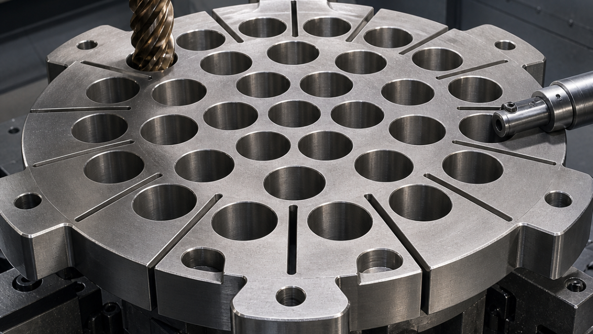
An Incoloy 800H furnace tube-support grid cannot be machined by drilling every bore and cutting every slot in sequence around the plate. That route concentrates heat, work-hardens the next entry and releases the thin ligaments unevenly. This hypothetical plan roughs the bore array in a checkerboard pattern, opens expansion slots before the final face skim, and assigns separate carbide tools to bore roughing, fine boring and slot-wall finishing.
Array tolerances and the free-state requirement
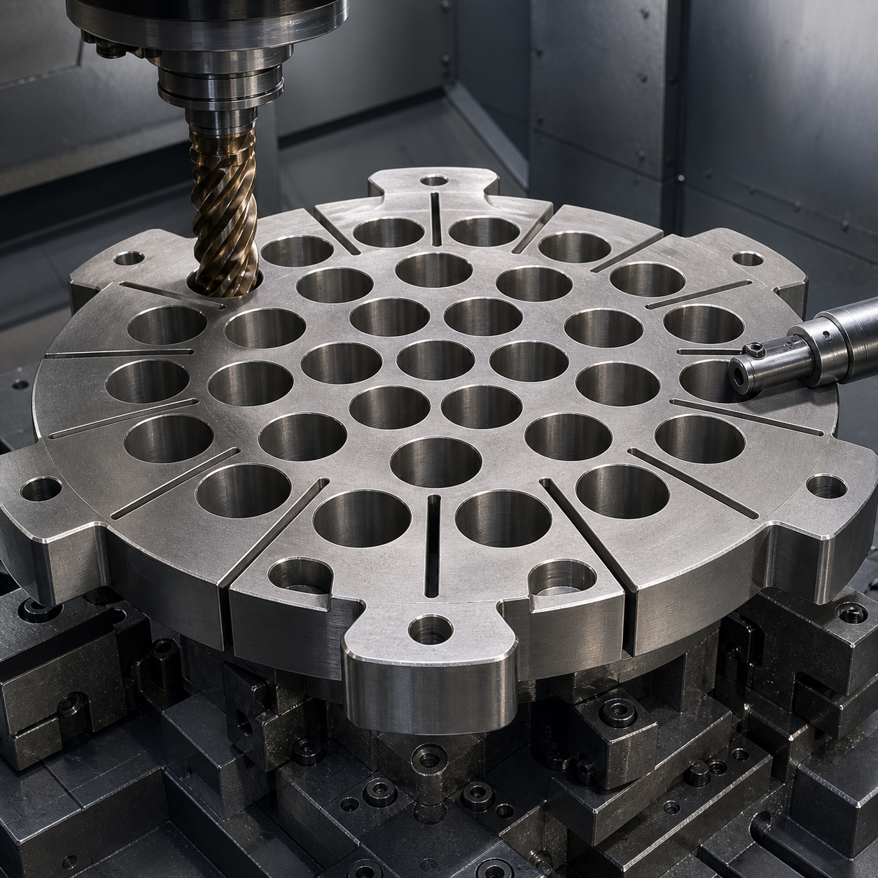
Datum face A, centre pilot B and clocking hole C locate 36 tube bores Ø18 H8 at true position 0.050 mm. Minimum ligament between neighbouring bores is 3.0 mm. Twelve radial expansion slots are 3.00 +0.050/0 mm wide, 10 mm deep and terminate at R1.50. Four mounting pads must remain coplanar within 0.080 mm after release; tube-bore finish is Ra 1.6 µm and the plate faces are Ra 3.2 µm. No burr may project into a bore or bridge a slot end.
The drawing accepts dimensions only after the grid is unclamped and stabilized. Fixture-flat results are recorded for process control but do not release the part.
Tool selection for heat-resistant alloy and narrow ligaments
| Drawing feature | Selected carbide tool and holder | Reason and rejected option |
|---|---|---|
| Scale and bulk stock | Ø20 five-flute variable-pitch AlTiN submicron-carbide rougher, 42° helix, R0.8, 0.04 mm edge hone, hydraulic holder | Tough edge and low radial engagement survive scale; a sharp aluminium cutter chips at the entry line. |
| Datum faces and pads | Ø50 high-feed face mill with six tough PVD-carbide inserts, 0.8 mm corner radii and one wiper insert, short arbor | Low axial depth limits heat; a solid end mill would require many overlapping hot passes. |
| Tube-bore opening | Ø14 indexable through-coolant drill with positive AlTiN carbide inserts, 140° effective point, rigid flange holder | Creates chip space quickly; a long solid drill would be costly and prone to notch wear at scale. |
| Bore semifinish | Ø12 five-flute unequal-pitch AlCrN carbide end mill, R0.5, 28 mm reach, shrink-fit holder | Helical interpolation leaves 0.15 mm diametral stock and corrects drill position. |
| Ø18 H8 finish | Positive R0.4 PVD-carbide fine-boring insert, medium-hone edge, through-coolant modular head on a short damped bar | Each bore receives wear compensation; a reamer cannot correct array position or local taper. |
| Expansion-slot roughing | Ø2.5 three-flute AlCrN carbide, 25° variable helix, reduced neck 12 mm, micro hydraulic chuck | Trochoidal entry keeps the 3 mm ligaments loaded gradually; full-width slotting concentrates heat. |
| Slot finish and R1.5 end | Ø3.0 four-flute AlTiN carbide, unequal pitch, R0.15, 11 mm cutting length, minimum projection | One compensated wall at a time controls width and end radius; a worn rougher cannot hold both. |
| Mounting holes and edge breaks | Ø10.2 through-coolant carbide drill, 140°, M12×1.75 five-flute AlCrN thread mill, plus Ø10 four-flute 90° chamfer tool | Thread milling limits torque and permits gauge correction; tapping risks seizure in work-hardened stock. |
Checkerboard roughing and stress release
The plate sits on three ground pads with clamps above thick mounting lobes. Face A is roughed, then tube holes are opened in a checkerboard order that never processes adjacent bores consecutively. The Ø12 helical tool restores position while leaving 0.15 mm diameter stock. Expansion slots are roughed in opposing pairs with 0.10 mm per wall remaining; a sacrificial backer supports each slot end.
The grid is released, thermally equalized and measured for bow. A light corrective setup then skims the four pads and A before final boring. Bores are finished from the centre outward with high-pressure filtered coolant, and the slot finisher alternates opposite radii. Notch wear, a straw-coloured rubbed band or rising spindle load retires the tool before it enters the next ligament.
Inspection and practical FAQ
A CMM establishes A-B-C and maps bore position, pad coplanarity and slot endpoints. A bore comparator measures Ø18 H8 at two depths and two directions; a profilometer samples Ra. Vision checks ligament width, R1.5 terminations and burr direction. Final flatness is measured on three free supports after temperature stabilization.
Why are Incoloy 800H tube bores roughed in a checkerboard order?
Spacing the cuts distributes heat and work hardening, protecting the 3 mm ligaments and the next tool entry.
Why fine-bore rather than ream the Ø18 H8 array?
Fine boring independently corrects diameter, taper and position after the plate has released stress.
When should the expansion slots be opened?
Rough them before the final face and bore finishing, then measure the released grid and restore functional datums.
Related guidance: notch-wear and heat control in nickel alloys and tool-wear signatures for change decisions.
中文: Incoloy 800H炉管支承栅板CNC配刀:管孔阵列与膨胀槽
Incoloy 800H炉管栅板不能沿圆周连续钻完孔再依次开槽;这样会把热量集中到相邻薄筋,并让下一次入刀落在加工硬化区。本案例采用棋盘式分散开孔、最终精面前释放膨胀槽,并把孔开粗、螺旋半精、精镗和槽壁精加工分配给不同硬质合金刀具。
图纸只接受自由状态尺寸
基准面A、中心定位B和定向孔C定位36个Ø18 H8管孔,位置度0.050 mm,孔间最小筋宽3.0 mm。十二条径向膨胀槽宽3.00 +0.050/0 mm、深10 mm、端部R1.50;四个安装垫松夹后共面0.080 mm。管孔Ra 1.6 µm,平面Ra 3.2 µm,不允许毛刺伸入孔内或跨接槽端。
耐热合金配刀矩阵
| 图纸特征 | 刀具、刃口与刀柄 | 为什么选它 |
|---|---|---|
| 氧化皮和大余量 | Ø20五刃不等距AlTiN亚微细晶硬质合金,42°,R0.8,刃口0.04 mm,液压刀柄 | 韧刃小径向吃刀跨过氧化皮,铝用锋利刃容易崩口。 |
| A面与安装垫 | Ø50高进给面铣刀,六片PVD韧性硬质合金R0.8刀片,含一片修光刃,短刀杆 | 浅轴向切深控制热量,减少多道接刀。 |
| 管孔开孔 | Ø14可转位内冷钻,正角AlTiN硬质合金刀片,有效钻尖140°,法兰柄 | 快速建立容屑空间,避免长整体钻在氧化皮处沟槽磨损。 |
| 孔半精 | Ø12五刃不等分AlCrN硬质合金,R0.5,悬伸28 mm,热缩柄 | 螺旋插补修孔位并留直径0.15 mm。 |
| Ø18 H8精加工 | R0.4正角PVD硬质合金精镗片,中等刃口钝化,内冷模块头和短减振杆 | 每孔独立补磨损和锥度,铰刀不能修阵列位置。 |
| 膨胀槽开粗 | Ø2.5三刃AlCrN,25°不等螺旋,缩颈12 mm,微型液压柄 | 摆线进刀逐步加载3 mm薄筋,拒绝满槽发热。 |
| 槽壁和R1.5 | Ø3.0四刃不等分AlTiN,R0.15,刃长11 mm,短悬伸 | 两壁分别补偿,开粗刀磨损后不兼做精刀。 |
| M12安装孔 | Ø10.2内冷硬质合金钻、140°,Ø8五刃AlCrN螺纹铣刀M12×1.75,Ø10四刃90°倒角刀 | 螺纹铣削低扭矩且可校中径,避免丝锥在硬化层咬死。 |
棋盘开孔和释放顺序
栅板放在三块研磨支点上,压板只落在厚安装耳。A面开粗后,以不连续加工相邻孔的棋盘顺序开Ø14孔;Ø12螺旋刀修正位置并留直径0.15 mm。膨胀槽按相对位置成对开粗,每壁留0.10 mm,牺牲背板支承R1.5端部。
松夹、均温并记录翘曲后,轻装夹修四垫与A面,再从中心向外精镗。槽精刀交替加工对径。沟槽磨损、稻草色摩擦带或负载上升都要求换刀,不能带到下一条薄筋。
检验与问题
三坐标建立A-B-C并绘制孔位、垫面共面和槽端图;孔径比较仪在两深度、两方向测Ø18 H8,轮廓仪抽查Ra。视觉测筋宽、R1.5和毛刺方向;最终平面度在均温后的三点自由支承上测量。
为什么800H孔阵列要棋盘式加工?
分散切削热和加工硬化,保护3 mm薄筋以及下一孔的入刀区。
Ø18 H8为何精镗而不是铰孔?
栅板释放应力后,每孔的尺寸、锥度和位置需要独立修正。
膨胀槽何时加工?
在最终精面和精孔前先开粗释放,松夹测量后再恢复功能基准。
参考:镍基合金沟槽磨损与热控制、刀具磨损信号诊断。
Français: Outils CNC pour grille Incoloy 800H : alésages et fentes de dilatation
Une progression circulaire accumulerait chaleur et écrouissage dans les ligaments. Le réseau est donc ébauché en damier, les fentes sont libérées avant la dernière reprise des faces et trois outils distincts ouvrent, semi-finissent puis alèsent chaque trou.
Conditions libres du plan
A-B-C placent 36 alésages Ø18 H8 à 0,050 mm, séparés par 3,0 mm minimum. Douze fentes font 3,00 +0,050/0 mm sur 10 mm, fin R1,50. Les quatre plots restent coplanaires à 0,080 mm après desserrage. Les trous demandent Ra 1,6 µm, sans bavure interne.
Carte des outils
| Fonction | Carbure et maintien | Décision |
|---|---|---|
| Calamine | Ø20, cinq dents variables AlTiN, 42°, R0,8, arête 0,04 mm, hydraulique | Arête robuste à faible engagement. |
| Faces | Tourteau Ø50, six plaquettes PVD R0,8 dont une racleuse | Faible profondeur et peu de raccords. |
| Ouverture | Foret indexable Ø14 arrosé, plaquettes AlTiN positives | Crée vite l’espace copeau. |
| Semi-finition | Ø12, cinq dents AlCrN, R0,5, portée 28 mm | Corrige la position, réserve 0,15 mm. |
| Ø18 H8 | Alésage fin PVD R0,4, arrosé, barre courte amortie | Compense chaque trou. |
| Fente brute | Ø2,5, trois dents AlCrN, 25°, col 12 mm | Trochoïde à faible chaleur. |
| Fente finie | Ø3,0, quatre dents AlTiN variables, R0,15 | Parois et R1,5 contrôlés. |
| M12 | Foret Ø10,2, fraise à fileter Ø8 AlCrN et chanfreineuse Ø10 | Faible couple, diamètre corrigible. |
Libération et mesure
Trois appuis portent la grille. Les trous non voisins sont ouverts successivement; 0,15 mm reste au diamètre. Les fentes opposées gardent 0,10 mm par paroi. Après desserrage et égalisation thermique, les plots et A sont repris, puis les trous sont alésés du centre vers l’extérieur. Usure en entaille, bande jaune ou charge montante retirent l’outil.
MMT, comparateur d’alésage, profilomètre et vision contrôlent positions, H8, Ra, ligaments et rayons. La planéité finale est mesurée sur trois appuis libres.
Pourquoi un ordre en damier?
Pour distribuer chaleur et écrouissage.
Pourquoi aléser fin?
Pour corriger chaque trou après libération.
Quand ouvrir les fentes?
Avant les dernières faces et alésages.
Voir l’usure des alliages nickel et les signatures d’usure.
Русский: Инструмент для решётки 800H: отверстия и температурные пазы
Последовательное сверление по окружности перегревает соседние перемычки и наклёпывает следующий вход. Поэтому отверстия черновятся в шахматном порядке, пазы раскрываются до окончательной плоскости, а открытие, полуфиниш и чистовая расточка имеют отдельные инструменты.
Свободные размеры
A-B-C размещают 36 отверстий Ø18 H8 с позицией 0,050 мм и перемычкой не менее 3,0 мм. Двенадцать пазов имеют ширину 3,00 +0,050/0 мм, глубину 10 мм и конец R1,50. Четыре площадки после разжима лежат в 0,080 мм. Отверстия требуют Ra 1,6 мкм без внутреннего заусенца.
Инструментальная схема
| Операция | Инструмент | Обоснование |
|---|---|---|
| Окалина | Ø20, пять переменных зубьев AlTiN, 42°, R0,8, кромка 0,04 мм | Прочная кромка. |
| Плоскости | Фреза Ø50, шесть PVD-пластин R0,8, одна зачистная | Малая глубина и мало стыков. |
| Открытие | Сверло Ø14 со сменными AlTiN-пластинами и внутренней СОЖ | Быстрое место для стружки. |
| Полуфиниш | Ø12, пять зубьев AlCrN, R0,5, вылет 28 мм | Исправляет позицию. |
| Ø18 H8 | Расточка PVD R0,4 с СОЖ на короткой демпфированной штанге | Каждое отверстие корректируется. |
| Паз грубо | Ø2,5, три зуба AlCrN, 25°, шейка 12 мм | Малая тепловая нагрузка. |
| Паз чисто | Ø3,0, четыре переменных зуба AlTiN, R0,15 | Контроль стенок и R1,5. |
| M12 | Сверло Ø10,2, резьбовая фреза Ø8 и фасочная Ø10 | Малый момент. |
Порядок и контроль
Решётка лежит на трёх опорах. Соседние отверстия не режутся подряд; на диаметр остаётся 0,15 мм. Противоположные пазы оставляют по 0,10 мм на стенку. После разжима и выравнивания температуры восстанавливаются A и площадки, затем отверстия идут от центра наружу. Канавочный износ, жёлтая полоса или рост нагрузки требуют замены.
КИМ, нутромер, профилометр и оптика проверяют позиции, H8, Ra, перемычки и радиусы. Плоскостность измеряется на трёх свободных точках.
Зачем шахматный порядок?
Для распределения тепла и наклёпа.
Почему расточка?
Для независимой коррекции после освобождения.
Когда делать пазы?
До окончательных плоскостей и отверстий.


