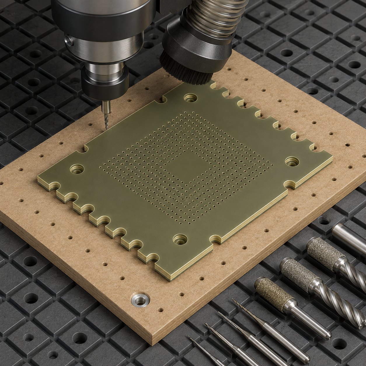
English: FR4 Test-Socket Adapter Plate CNC Tool Selection for Castellated Edges and Micro Via Holes
The search intent here is practical: selecting CNC tools for an FR4 test-socket adapter plate where micro via holes, castellated edge reliefs and screw counterbores must be clean without delaminating the glass-epoxy laminate. The correct tooling plan treats dust, backing support and compression geometry as drawing requirements, not shop-floor afterthoughts.
Drawing interpretation
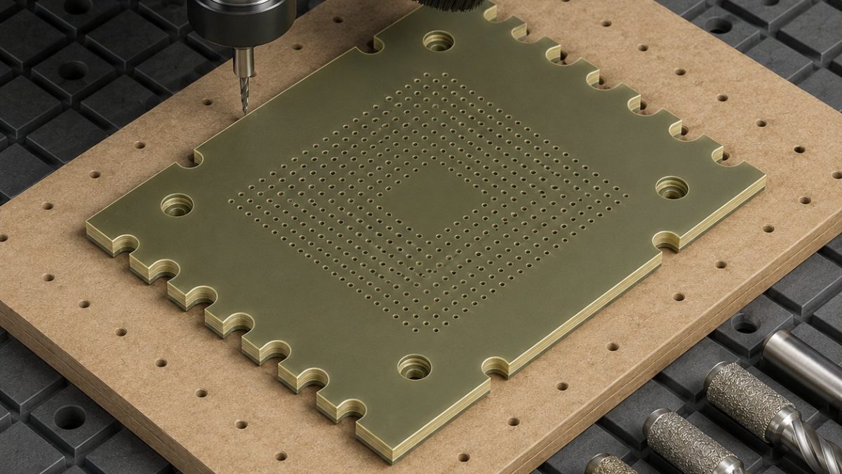
The hypothetical adapter has a dense Ø0.45 mm via field, semi-circular castellations on two edges, four counterbored screw pockets and a central keep-out window. The plate is thin enough to flutter, so the fixture uses a sacrificial backer and vacuum support similar in logic to vacuum support for thin plates. For other abrasive laminate behaviour, compare abrasive laminate tool selection.
Localized feature-to-tool decision
| Feature | Tool selected | Rejected alternative |
|---|---|---|
| Panel outline and edge datum | Ø3 mm diamond-coated compression router, 2-flute, short flute length | A conventional carbide end mill frays the top or bottom glass layer. |
| Castellated half-holes | Diamond-coated burr router, climb-only spring pass on supported edge | Drilling after profiling is rejected because the half-hole lip chips. |
| Ø0.45 mm via holes | Carbide PCB micro drill with high-speed spindle and phenolic entry sheet | A peck cycle with a general micro drill leaves glass whiskers. |
| Counterbored screw pockets | Two-step carbide drill plus flat-bottom micro end mill | A single counterbore tool pulls laminate at the pocket floor. |
| Final edge break | Very light PCD chamfer tool, dust extraction active | Abrasive hand sanding changes edge registration. |
Process, chips and quality gate
Drill the via field before releasing the outline, then route castellations while the backer is still intact. Use vacuum plus perimeter tabs, high rpm, small chip load and continuous dust extraction. Inspection uses optical hole breakout, edge profile overlay, screw-head seating check, thickness measurement after deburring and a no-loose-fibre wipe test.
中文: FR4测试座转接板半孔边与微孔钻削配刀
这类 FR4 测试座转接板的搜索重点是:半孔边、密集微孔和沉孔怎样选刀才不分层、不起玻纤毛刺。配刀时要把背板支撑、吸尘和压缩切削几何当作图纸要求来处理。
图纸读法
假设零件有 Ø0.45 mm 微孔阵列、两侧半圆 castellated 边、四个螺钉沉孔和中间避让窗口。板材薄,不能只靠压板;需要牺牲背板、真空支撑和外框留桥。
特征配刀表
| 特征 | 选用刀具 | 不用的方案 |
|---|---|---|
| 外形与基准边 | Ø3 mm 金刚石涂层压缩铣刀,两刃短刃长 | 普通硬质合金立铣刀容易上下表层撕裂。 |
| 半孔边 | 金刚石涂层毛刺铣刀,支撑状态下顺铣精修 | 先外形后钻孔会崩半孔口。 |
| Ø0.45 mm 微孔 | PCB 硬质合金微钻,高速主轴加入口盖板 | 普通微钻低速啄钻会留下玻纤丝。 |
| 螺钉沉孔 | 阶梯钻预孔后小平底铣刀清底 | 单支沉孔刀容易拉起孔底层压材料。 |
| 边缘倒钝 | PCD 微倒角刀,吸尘开启 | 手砂会改变定位边尺寸。 |
工艺与检验
先加工微孔阵列,再在背板完整时加工半孔边。刀路高转速、小进给、连续吸尘,最后切断外框留桥。检验用显微镜看孔口、投影比对半孔轮廓、检查螺钉坐面、测厚并做无松散玻纤擦拭检查。
Français: Outils CNC pour plaque FR4 avec demi-trous et micro-perçages
Pour une plaque adaptatrice de test en FR4, le choix d’outils vise à éviter le délaminage autour des micro-trous, des demi-trous de bord et des lamages. Le support arrière et l’aspiration des poussières sont des éléments du procédé.
Contraintes du plan
Le plan impose un champ de micro-perçages, des encoches demi-circulaires sur deux bords et des poches de vis peu profondes. La plaque reste tenue sur un martyr jusqu’à la dernière opération de contournage.
Table outil-fonction
| Fonction | Outil | Raison |
|---|---|---|
| Profil extérieur | Fraise compression diamantée Ø3 mm | Coupe les deux peaux sans arrachement. |
| Demi-trous de bord | Fraise diamantée courte avec passe de reprise | Limite l’écaillage du verre époxy. |
| Micro-trous | Micro-foret carbure PCB avec feuille d’entrée | Meilleure stabilité et sortie plus propre. |
| Lamages | Perçage étagé puis fraise plate carbure | Fond de poche plus régulier qu’un outil unique. |
| Arêtes | Mini fraise PCD à chanfreiner | Évite le ponçage dimensionnel. |
Contrôle qualité
Le contrôle se fait au microscope sur les trous, par projection sur les demi-trous, par essai d’assise des vis et par essuyage pour repérer les fibres libres.
Русский: Инструмент для FR4 платы с микроперфорацией
Для адаптерной платы FR4 важно подобрать инструмент так, чтобы микроперфорация, полукруглые края и цековки не дали расслоения. Основа процесса — опорная плита и удаление абразивной пыли.
Что важно на чертеже
Массив отверстий мал, края имеют полукруглые вырезы, а винтовые места требуют ровного дна. Деталь держат на жертвенной подложке до последнего прохода.
Подбор инструмента
| Элемент | Инструмент | Почему |
|---|---|---|
| Контур | Ø3 мм алмазное компрессионное фрезерование | Снижает расслоение верхнего и нижнего слоя. |
| Полуотверстия края | Короткая алмазная фреза с чистовым проходом | Сохраняет кромку без скола. |
| Микроотверстия | PCB микросверло из карбида | Меньше стеклянных волокон на выходе. |
| Цековки | Ступенчатое сверло и плоская микрофреза | Дает ровное дно. |
| Фаска | Малая PCD фасочная фреза | Лучше ручного шлифования. |
FAQ
Should FR4 castellated edges be drilled before or after routing?
They should usually be drilled or supported before final edge release so the half-hole lip is not left unsupported.
Are diamond-coated tools necessary for a short FR4 job?
For reliable edge quality they are strongly preferred because glass fibres quickly dull ordinary carbide.
How is FR4 burr quality inspected?
Use microscope inspection, wipe testing for loose fibres and profile overlay on the castellated edge.