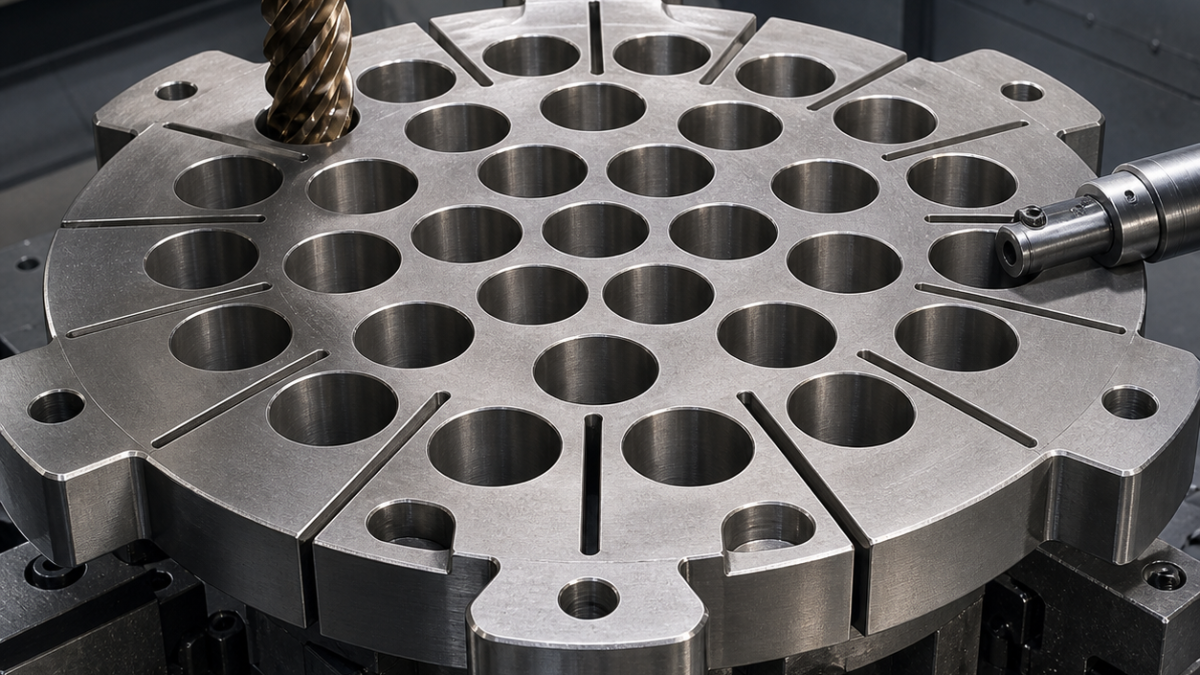
English: Incoloy 800H Grid Tooling for a Bore Array and Expansion Slots
The updated search answer is how to keep an Incoloy 800H bore array on pitch while expansion slots release a hot, work-hardened plate. Hole order, ligament temperature and the moment each slot is opened determine whether the final grid stays flat.
An Incoloy 800H furnace tube-support grid cannot be machined by drilling every bore and cutting every slot in sequence around the plate. That route concentrates heat, work-hardens the next entry and releases the thin ligaments unevenly. This hypothetical plan roughs the bore array in a checkerboard pattern, opens expansion slots before the final face skim, and assigns separate carbide tools to bore roughing, fine boring and slot-wall finishing.
Array tolerances and the free-state requirement
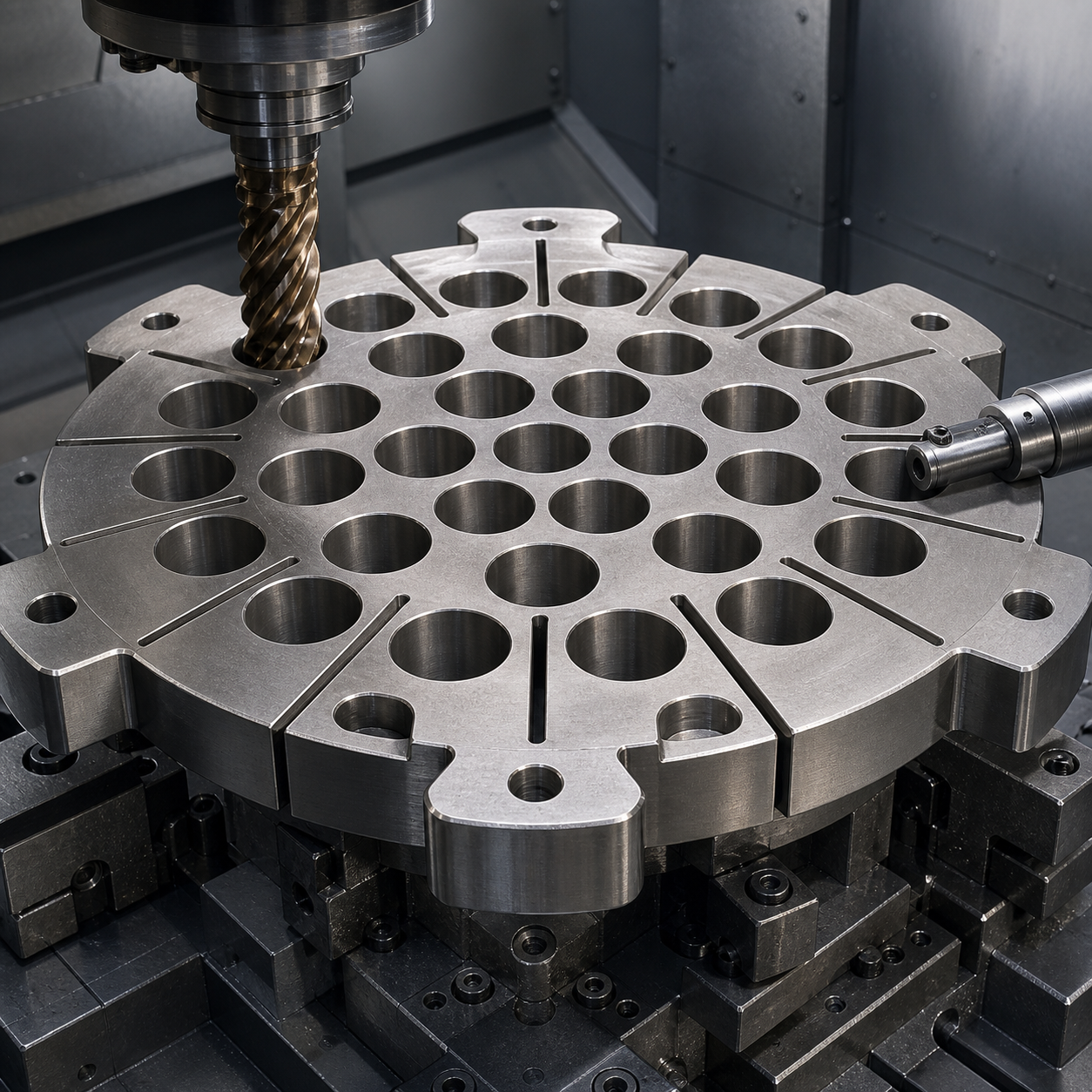
Datum face A, centre pilot B and clocking hole C locate 36 tube bores Ø18 H8 at true position 0.050 mm. Minimum ligament between neighbouring bores is 3.0 mm. Twelve radial expansion slots are 3.00 +0.050/0 mm wide, 10 mm deep and terminate at R1.50. Four mounting pads must remain coplanar within 0.080 mm after release; tube-bore finish is Ra 1.6 µm and the plate faces are Ra 3.2 µm. No burr may project into a bore or bridge a slot end.
The drawing accepts dimensions only after the grid is unclamped and stabilized. Fixture-flat results are recorded for process control but do not release the part.
Tool selection for heat-resistant alloy and narrow ligaments
| Drawing feature | Selected carbide tool and holder | Reason and rejected option |
|---|---|---|
| Scale and bulk stock | Ø20 five-flute variable-pitch AlTiN submicron-carbide rougher, 42° helix, R0.8, 0.04 mm edge hone, hydraulic holder | Tough edge and low radial engagement survive scale; a sharp aluminium cutter chips at the entry line. |
| Datum faces and pads | Ø50 high-feed face mill with six tough PVD-carbide inserts, 0.8 mm corner radii and one wiper insert, short arbor | Low axial depth limits heat; a solid end mill would require many overlapping hot passes. |
| Tube-bore opening | Ø14 indexable through-coolant drill with positive AlTiN carbide inserts, 140° effective point, rigid flange holder | Creates chip space quickly; a long solid drill would be costly and prone to notch wear at scale. |
| Bore semifinish | Ø12 five-flute unequal-pitch AlCrN carbide end mill, R0.5, 28 mm reach, shrink-fit holder | Helical interpolation leaves 0.15 mm diametral stock and corrects drill position. |
| Ø18 H8 finish | Positive R0.4 PVD-carbide fine-boring insert, medium-hone edge, through-coolant modular head on a short damped bar | Each bore receives wear compensation; a reamer cannot correct array position or local taper. |
| Expansion-slot roughing | Ø2.5 three-flute AlCrN carbide, 25° variable helix, reduced neck 12 mm, micro hydraulic chuck | Trochoidal entry keeps the 3 mm ligaments loaded gradually; full-width slotting concentrates heat. |
| Slot finish and R1.5 end | Ø3.0 four-flute AlTiN carbide, unequal pitch, R0.15, 11 mm cutting length, minimum projection | One compensated wall at a time controls width and end radius; a worn rougher cannot hold both. |
| Mounting holes and edge breaks | Ø10.2 through-coolant carbide drill, 140°, M12×1.75 five-flute AlCrN thread mill, plus Ø10 four-flute 90° chamfer tool | Thread milling limits torque and permits gauge correction; tapping risks seizure in work-hardened stock. |
Checkerboard roughing and stress release
The plate sits on three ground pads with clamps above thick mounting lobes. Face A is roughed, then tube holes are opened in a checkerboard order that never processes adjacent bores consecutively. The Ø12 helical tool restores position while leaving 0.15 mm diameter stock. Expansion slots are roughed in opposing pairs with 0.10 mm per wall remaining; a sacrificial backer supports each slot end.
The grid is released, thermally equalized and measured for bow. A light corrective setup then skims the four pads and A before final boring. Bores are finished from the centre outward with high-pressure filtered coolant, and the slot finisher alternates opposite radii. Notch wear, a straw-coloured rubbed band or rising spindle load retires the tool before it enters the next ligament.
Inspection and practical FAQ
A CMM establishes A-B-C and maps bore position, pad coplanarity and slot endpoints. A bore comparator measures Ø18 H8 at two depths and two directions; a profilometer samples Ra. Vision checks ligament width, R1.5 terminations and burr direction. Final flatness is measured on three free supports after temperature stabilization.
Why are Incoloy 800H tube bores roughed in a checkerboard order?
Spacing the cuts distributes heat and work hardening, protecting the 3 mm ligaments and the next tool entry.
Why fine-bore rather than ream the Ø18 H8 array?
Fine boring independently corrects diameter, taper and position after the plate has released stress.
When should the expansion slots be opened?
Rough them before the final face and bore finishing, then measure the released grid and restore functional datums.
Related guidance: notch-wear and heat control in nickel alloys and tool-wear signatures for change decisions.
Added thermal-sequence and tool-life gate
Spot only the current checkerboard group, then pilot-drill with an 8 mm through-coolant carbide drill and helically semifinish with a 12 mm five-flute AlTiN radius mill. Leave each bore 0.15 mm for a damped fine-boring head after the neighboring group cools. Open expansion slots with a 4 mm four-flute variable-helix carbide tool before the final face skim; a thin slitting saw is rejected because side wander can scar the ligaments.
| Drawing checkpoint | Tool / method | Acceptance logic |
|---|---|---|
| Bore group | Checkerboard drill and helical semifinish | Pitch and zone temperature |
| H8 bore | Damped fine-boring head, 0.15 mm stock | Air-gauge size and CMM axis |
| Expansion slot | 4 mm 4-flute variable-helix carbide | Slot width and free flatness |
Inspection and stop rules
Map plate temperature and spindle load by grid zone, not only by tool number. Probe three reference bores after every group, inspect notch wear at the depth-of-cut line, and stop before the next group if pitch drift exceeds the process limit. Final inspection combines CMM pitch, air-gauge diameter, slot width and free-state flatness after thermal stabilization.
Related tooling paths: Inconel deep-bore tooling; AL-6XN tandem-bore tooling.
Focused FAQ
Why checkerboard order? It separates adjacent heat sources. Why bore after semifinishing? Fine boring corrects size and axis instead of following drill wander. Why slot before final facing? The skim removes the small release distortion.
For alloy-first comparison across pockets, holes, seats, grooves and thin sections, use the nickel-alloy CNC tooling decision hub.


