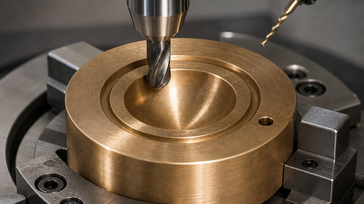
English: C93200 Bronze Slipper Pad CNC Tool Selection for Spherical Socket and Lapping Face
A C93200 hydraulic slipper pad succeeds when the spherical socket, hydrostatic pocket and future lapping face are treated as one geometry chain. Sharp uncoated carbide prevents leaded bronze from smearing, a swept single-point tool finishes the socket without dwelling at the pole, and the sliding face keeps measured lapping stock rather than being polished to final size in the machining centre. This hypothetical case maps every oil feature to a separate low-force tool.
Start from the ball centre, not the outside diameter
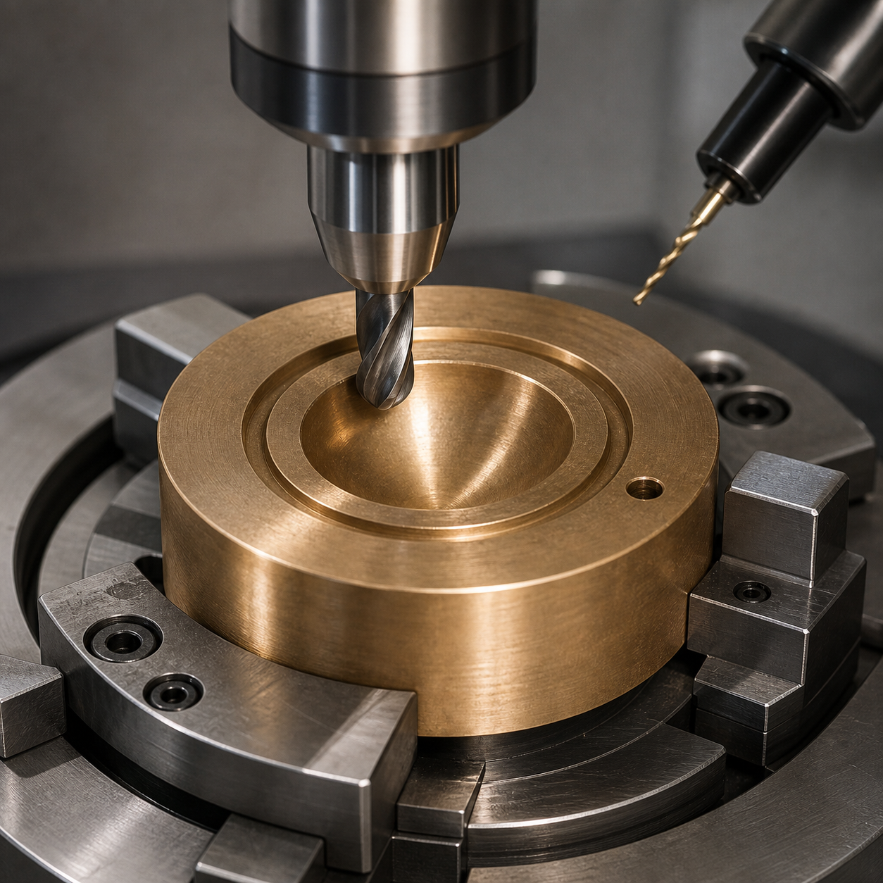
The drawing defines spherical socket S as the primary functional feature. Its radius is SR12.50 ±0.010 mm and its centre is 8.00 ±0.015 mm from sliding datum A. Face A has 0.003 mm flatness after lapping and stays parallel to the socket centreline within 0.005 mm. A Ø16.0 hydrostatic pocket is 0.40 mm deep, surrounded by a 1.00 × 0.30 mm annular restrictor groove. A central Ø0.80 +0.010/0 mm metering hole connects the socket to the pocket. The Ø32 h7 outside diameter is only a handling datum, not the origin for socket correction.
Machining therefore leaves 0.015 mm on face A for the separate lapping operation. Removing that stock early would shift the hydraulic gap after the sphere had already been accepted.
Low-force feature-to-tool plan
| Feature | Selected tool, edge and holder | Rationale and alternative rejected |
|---|---|---|
| Blank OD and reference face | Ø12 three-flute uncoated micrograin-carbide end mill, polished 35° helix, R0.3, 0.01 mm edge preparation, hydraulic holder | The positive edge shears the soft matrix; a honed steel-grade tool burnishes lead-rich areas. |
| Spherical socket roughing | Ø8 two-flute uncoated polished-carbide ball mill R4, 14 mm reach, shrink-fit holder | A spiral path leaves 0.12 mm normal stock; excessive flute count traps soft chips. |
| Spherical socket finishing | R0.2 polished uncoated-carbide insert in a swept spherical-boring attachment, positive 18° rake, rigid short cartridge | Maintains cutting speed through the pole; a ball mill rubs near its zero-speed centre. |
| Hydrostatic pocket | Ø6 single-flute O-geometry uncoated carbide, polished face, R0.1, precision collet | Large chip space prevents recutting; a four-flute cutter can pack bronze into the floor. |
| Restrictor groove | Ø1.0 two-flute straight-groove carbide slot mill, polished lands, 1.2 mm cutting length, micro hydraulic chuck | Two compensated circular passes control both walls; a fixed form cutter cannot correct asymmetric wear. |
| Metering orifice | Ø0.76 two-flute carbide drill, 130° split point, internal coolant, followed by Ø0.80 four-flute straight carbide reamer with 0.5 mm short lands | The reamer defines flow diameter; laser drilling is unnecessary and can leave a recast layer in this hypothetical route. |
| Lapping-stock face | Single-edge PCD fly cutter Ø24 sweep, R0.4, balanced arbor, preset to leave 0.015 mm | Produces uniform stock; finish lapping inside the machine would contaminate guides and erase the datum allowance. |
| Oil-edge breaks | Ø3 single-flute polished carbide 90° chamfer tool, 0.05 mm break | A brush could roll bronze into the Ø0.80 orifice. |
Two nests and a controlled lapping allowance
Operation one holds the blank on three broad soft pads and establishes the outside diameter, back face and rough socket. A helical ramp keeps the ball mill moving, and filtered coolant carries chips away from the spherical floor. After probing the rough sphere, the swept boring attachment finishes from mouth to pole in one continuous arc; it never pauses at the centre.
Operation two locates on a qualified master-ball nest with a light axial clamp outside the future sliding band. The pocket, groove and metering hole are now positioned from S rather than from the OD. The fly cutter then creates uniform lapping stock on A. A waxy smear, intermittent torque rise or an orifice exit lip indicates a dull edge. Abrasive lapping occurs in a separate area, followed by ultrasonic cleaning compatible with the specified bronze and hydraulic service.
Inspection tied to hydraulic function
A calibrated sphere and contact scan verify socket radius, form and centre height. Before lapping, a CMM checks the pocket and groove relative to S; after lapping, an optical flat or qualified interferometric method checks A flatness. A profile trace measures groove width and depth. The metering hole is verified by pin and a controlled flow test, because diameter alone will not reveal a partial burr.
What cutter should finish a bronze slipper socket?
A positive polished carbide single-point edge swept around the sphere avoids the near-zero cutting speed at the centre of a ball end mill.
Why leave stock for lapping the slipper face?
The separate lapping step produces the functional flatness; machining to final thickness first would move the hydraulic gap when that stock is removed.
How is a 0.8 mm metering hole protected from burrs?
Use a short drill-and-ream sequence, support the exit, add a 0.05 mm programmed break and verify actual flow after cleaning.
Related cases: bronze bearing bore and oil-groove tooling and functional contact-surface finishing.


