English: Niobium RF Flange Tooling for a Seal Land and Thin Weld Lip
For a niobium RF flange, the decisive question is how to keep the seal land clean and the weld lip concentric while ductile chips try to fold over every edge. The revised plan separates reference creation, lip support and contamination control.
A high-purity niobium RF-cavity flange demands more than a sharp aluminium cutter. Niobium is ductile enough to fold a burr across the RF surface, and any tool previously used on steel can carry unwanted particles into a later joining or cleaning process. This hypothetical plan uses dedicated polished uncoated carbide, low-pressure soft-jaw support and a final cut that moves away from the 0.60 mm weld lip rather than pressing toward it.

Cleanliness notes are treated as drawing features
Beam-pipe bore A is Ø54.00 +0.020/0 mm and establishes the axis of RF seal land B. B is 6.0 mm wide, flat within 0.010 mm, concentric to A within 0.015 mm and specified at Ra 0.4 µm. The concentric weld lip is 0.60 ±0.030 mm thick and 2.50 mm long. Six alignment holes are Ø4 H7 at true position 0.020 mm. The print prohibits rolled burrs, embedded ferrous particles and polishing across B; the manufacturing plan therefore records tool history and fixture-contact materials.
The lip is measured after unclamping. A dimension taken only under jaw load can hide springback and is not used to release the part.
Dedicated sharp-edge tool selection
| Drawing feature | Selected tool, grade and reach | Why it is selected |
|---|---|---|
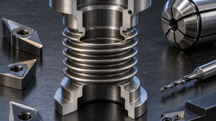
| Forged blank OD and back relief | Ø10 three-flute uncoated micrograin-carbide end mill, polished 35° helix, R0.5, 0.02 mm edge preparation, 18 mm reach, hydraulic holder | Enough edge strength for interrupted stock while retaining positive shear; a heavily honed coated cutter rubs the ductile metal. |
| Datum face semifinish | Ground DCGT 11T302 uncoated carbide insert, 18° polished rake, R0.2, dedicated positive holder | Produces a continuous chip at light depth; a steel-finishing insert carries both a duller edge and contamination history. |
| Ø54 bore roughing | Ø12 three-flute polished uncoated-carbide helical end mill, variable pitch, 25 mm reach, shrink-fit holder | Helical interpolation controls stock without a long stringy boring chip. |
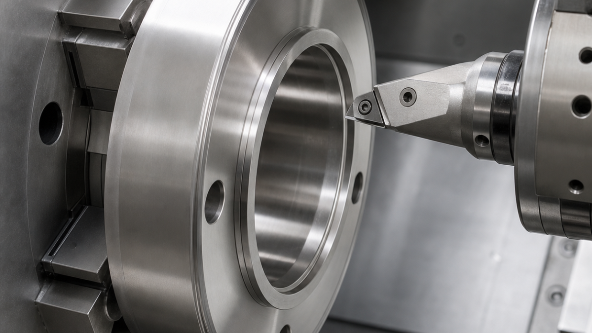
| Ø54 bore finish | R0.2 polished positive micrograin-carbide fine-boring insert on a short balanced bar, 0.005 mm maximum edge hone | Corrects taper and axis A; a reamer can smear and follow the semi-finished bore. |
| RF seal land B | Single-edge Ø20 sweep tool with polished uncoated-carbide insert, R0.8, balanced dedicated arbor, minimum projection | One outward spiral avoids overlapping insert tracks; abrasive polishing is rejected on the functional land. |
| 0.60 mm weld lip | 0.80 mm ground uncoated micrograin-carbide grooving blade, 20° positive polished rake, R0.05 corners, rigid blade block | Roughs the relief without loading the lip; a neutral coated blade pushes and folds the free edge. |
| Ø4 H7 alignment holes | Ø3.90 two-flute polished carbide drill, 130° split point, followed by Ø4 six-flute straight uncoated-carbide reamer with short lands | Short engagement limits galling; interpolation risks lobing at the tight fit. |
| Controlled edge breaks | Ø6 single-flute polished carbide 90° chamfer cutter, 0.05 mm programmed break, precision collet | A manual scraper can drag a burr toward B. |
Process route for chips, heat and the fragile lip
All cutters, collets and contact pads are dedicated to qualified non-ferrous work and cleaned before setup. Operation one grips sacrificial stock in capped soft jaws and roughs the OD, back relief and bore. Adaptive paths use constant engagement; chip-breaking arcs periodically reduce the continuous ribbon without dwelling. Coolant or clean air is used only according to the downstream cleanliness specification, never assumed from a generic niobium recipe.
Operation two locates on A with a broad relieved polymer interface and records jaw torque. The bore and alignment holes are finished before the lip is released. The grooving blade creates the undercut in two axial levels, leaving 0.08 mm on the lip; after a temperature pause, a new edge finishes from the free end toward supported stock. The RF land is cut last with an outward spiral. A shiny folded edge, rising thrust or stringy chip wrapping the lip stops the cycle.
Free-state verification and FAQ
A CMM builds A-B and checks the hole circle. Air gauging or a qualified bore comparator measures Ø54, white-light metrology checks lip thickness without probe force, and a profilometer traces B in the radial direction. Flatness and concentricity are repeated after the fixture releases. Final visual inspection under controlled lighting checks burr direction, scratches and foreign particles; no claim is made about downstream cavity acceptance beyond the hypothetical drawing.
What carbide geometry works for machining niobium?
A dedicated uncoated micrograin edge with polished positive rake and only a minimal hone cuts rather than pushes the ductile metal.
How is a thin niobium weld lip kept from folding?
Leave support until late, use a narrow positive grooving blade, finish from the free end toward supported material and inspect after unclamping.
Why are tools dedicated to niobium work?
The drawing treats foreign-particle transfer as a reject risk, so tool history and fixture-contact materials are part of process control.
Related reading: thin-lip tool reach in molybdenum and vacuum-component datum and cleanliness planning.
Added decision gate: edge condition and cleanliness
Reserve one polished uncoated tool set for niobium only. Finish the beam bore and seal land before releasing the lip; use a 6 mm three-flute polished end mill for local relief, a short fine-boring bar for the bore, and a 0.8 mm reverse chamfer tool for hidden edges. Reject steel-used cutters even if sharp because embedded debris can transfer to the RF surface.
| Drawing checkpoint | Tool / method | Acceptance logic |
|---|---|---|
| Seal land | Dedicated polished carbide; low-pressure fixture | No folded burr or wipe-test residue |
| Thin weld lip | Sharp finish insert; support ring retained | Optical thickness and bore runout |
| Hidden bore edge | 0.8 mm reverse chamfer tool | Magnified burr-height check |
Inspection and stop rules
Record spindle load, burr height and wipe-test result at fixed intervals. Probe bore-to-land runout in the fixture, measure lip thickness optically after release, and use a clean-room compatible replica only where direct stylus access would mark the surface.
Related tooling paths: niobium injector faceplate tooling; RF heat-spreader tooling.
Focused FAQ
Why uncoated carbide? It permits a sharper polished edge and avoids a warm adhesive interface. Why finish the lip last? The remaining ring supports the seal geometry. When is the tool retired? At burr growth, load drift or any cleanliness failure.