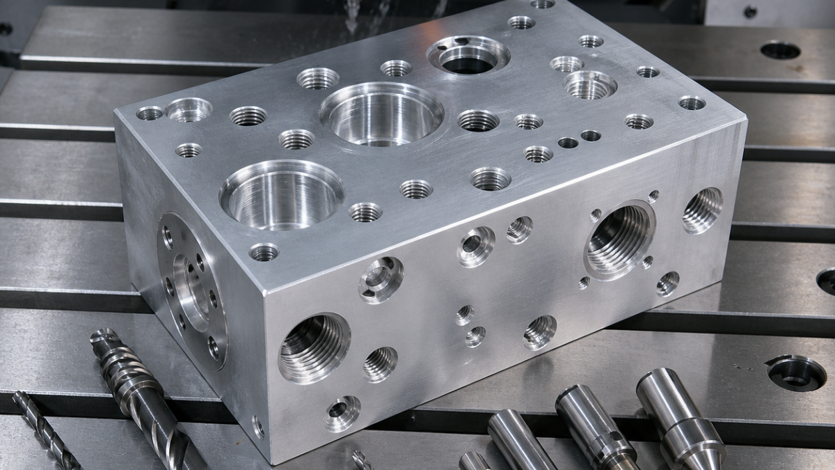
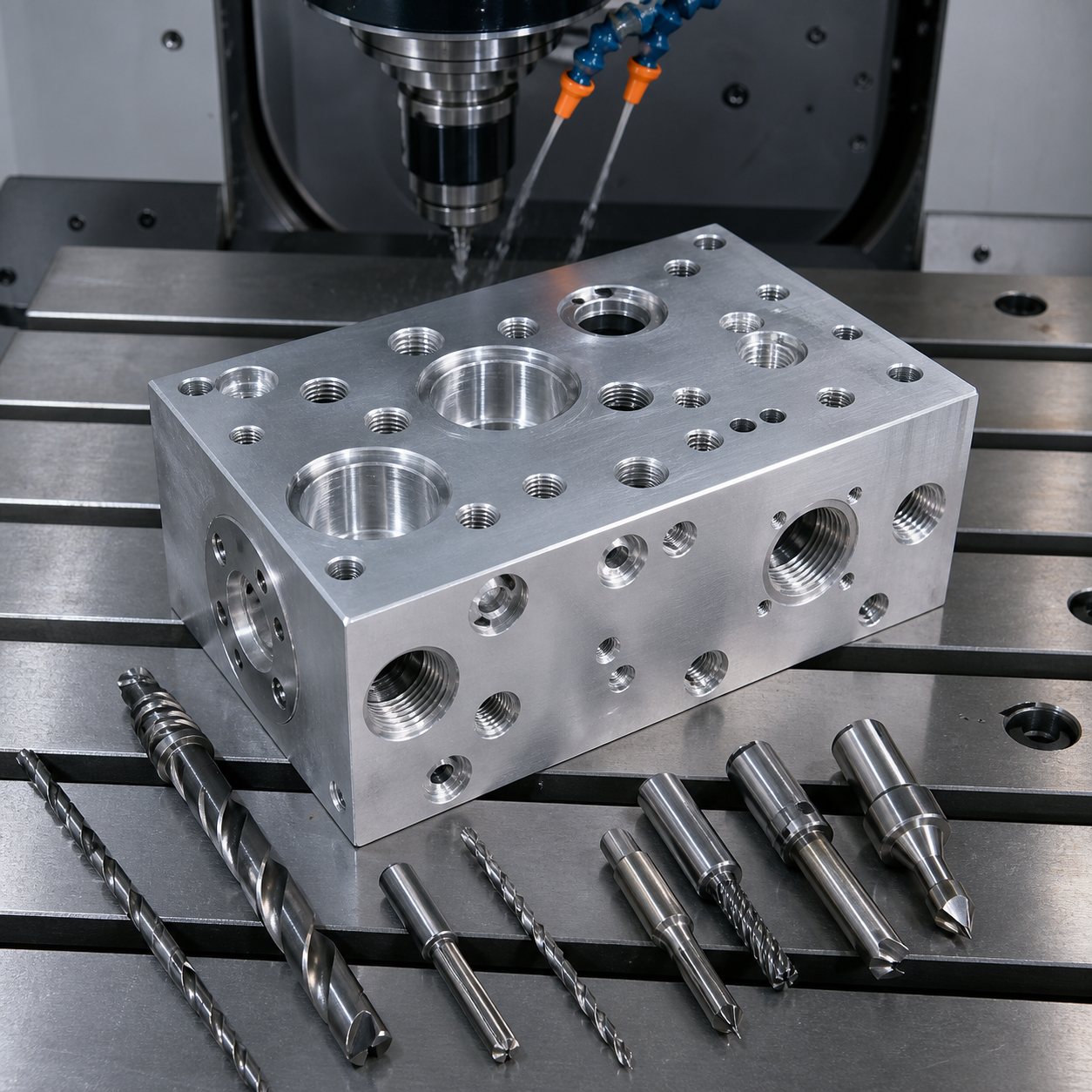
A 7075 aluminum hydraulic manifold machining plan is primarily a holemaking and risk-control problem. The drawing may look like a simple block, but intersecting passages, long diameter-to-depth ratios, threaded ports and leak-tight sealing faces create hidden failure modes. This case develops the process from functional requirements instead of treating every hole as an isolated drilling operation.
Drawing Assumptions and Critical Characteristics
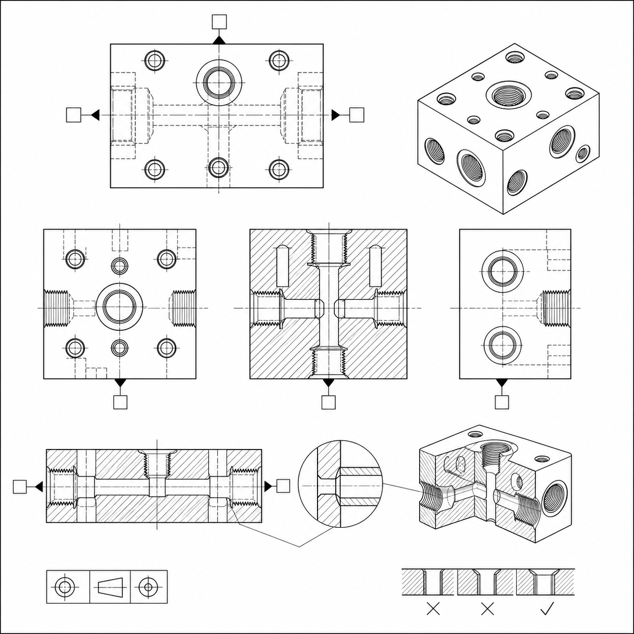
The assumed material is 7075-T6 or T651. Before programming, identify the primary sealing face, mounting datums, valve cavities, cross-hole intersections and plugs that close temporary drill access. The highest-risk characteristics are passage position, minimum wall thickness between bores, port thread depth, spotface flatness and burr-free intersections. A coordinate mistake can connect the wrong circuit even when every diameter measures correctly.
Datum, Fixturing and Setup Logic
Machine the broad sealing face as datum A, then establish perpendicular faces B and C. Use a probing cycle to verify block orientation before each indexed setup. A tombstone or four-axis fixture can reduce re-clamping, but only if the rotary center and work offset are qualified. Support the block near the cutting zone without distorting the sealing face. Keep one traceable setup sheet that maps every port to its drawing identifier and tool number.
Tooling Matrix
| Feature | Preferred tool | Process control |
|---|---|---|
| Datum and sealing faces | High-positive aluminum face mill or polished PCD cutter | Single controlled finish pass; protect the face after machining |
| Long passages | Through-coolant carbide drill with polished flute | Pilot depth, runout check, chip evacuation and depth monitoring |
| Valve cavities | Step drill, precision boring tool or reamer | Leave finish stock; measure before final sizing |
| Threaded ports | Thread mill for valuable parts; form/cut tap where qualified | Gauge effective depth and verify sealing thread specification |
| Cross-hole burrs | Back-chamfer tool, flexible abrasive or controlled thermal deburr | Borescope confirmation and cleanliness validation |
Recommended Process Sequence
- Review the hydraulic circuit and create a port-to-tool checklist.
- Face datum A, then machine B and C; probe the stock and record actual size.
- Rough external pockets and noncritical cavities before precision bores.
- Drill the longest passages from the most stable orientation, using through-tool coolant and controlled pecking only when chips require it.
- Machine intersecting holes and temporary access ports; deburr intersections before plugs hide them.
- Finish valve cavities, reamed bores and sealing spotfaces after heavy drilling.
- Thread ports, clean every circuit, perform pressure/leak testing and complete final inspection.
Starting Data and Validation
For polished carbide tools in stable 7075-T6 machining, a cutting-speed window around 180-350 m/min is a common starting region, but drill diameter, coolant pressure, flute length and machine limits control the final value. Use the tool maker’s chip-load table, calculate feed from rpm and flute count, then validate chip shape, spindle load, hole size and exit burr. Reduce speed or change the cycle when chips recut or pack in the flute; simply adding more pecks can increase heat and dwell marks.
Failure Modes and Countermeasures
- Drill wander: use a qualified spot/pilot geometry, short initial engagement and verified runout.
- Chip packing: improve through-coolant flow, retract strategy and flute polish; inspect coolant filtration.
- Cross-hole burrs: plan access for back deburring and inspect with a borescope before plugging.
- Sealing-face scratches: finish late, use dedicated soft handling surfaces and separate chips from finished parts.
- Wrong circuit connection: use probing, port mapping and an independent program review.
Inspection and Cleanliness Plan
Inspect datums and sealing faces on a CMM or surface plate, then verify passage location, cavity size, thread gauges and minimum wall condition. Use a borescope for intersections and a controlled flushing process for trapped chips. Final acceptance should include the specified pressure or leak test and a documented cleanliness standard; dimensional inspection alone cannot prove that a hydraulic manifold is ready for service.
中文工艺方案
7075 铝液压阀块的难点不是孔的数量,而是深孔偏斜、交叉孔内毛刺、密封面划伤和油路接错。应先从液压原理和图纸功能出发,把每个接口、阀腔、堵头孔与刀具编号对应起来。以密封大平面建立 A 基准,再建立 B、C 基准,每次分度装夹后都用探头确认方向和零点。
深孔优先采用内冷硬质合金钻,先验证跳动、冷却压力和排屑状态。交叉孔加工完成后,在堵头封闭之前用反向倒角刀、柔性磨料或经过验证的去毛刺工艺处理,并用内窥镜确认。精密阀腔和密封端面安排在大余量钻削之后,避免热量和夹紧应力影响最终尺寸。
最终检验除孔径、位置、螺纹和密封面外,还要包含油路冲洗、清洁度、压力或泄漏测试。尺寸合格不等于内部没有残屑,因此清洁与检验必须作为正式工序写入流程。
Résumé français
Pour un bloc hydraulique en aluminium 7075, les risques majeurs sont la déviation des perçages profonds, les bavures aux intersections, les erreurs de circuit et les rayures sur les faces d’étanchéité. Les références A, B et C sont créées avant les perçages, puis chaque orientation est vérifiée par palpage.
Les passages longs utilisent des forets carbure à arrosage central. Les intersections sont ébavurées et contrôlées par endoscope avant la pose des bouchons. Les alésages de distributeur et les portées d’étanchéité sont finis après les opérations lourdes. Le contrôle final comprend les dimensions, la propreté interne et l’essai de pression ou de fuite.
Русское резюме
При обработке гидравлического блока из алюминия 7075 главные риски связаны с уводом глубоких отверстий, заусенцами в пересечениях каналов, ошибкой соединения контуров и повреждением уплотнительных поверхностей. Базы A, B и C создают заранее, а каждую ориентацию проверяют щупом.
Длинные каналы сверлят твердосплавными сверлами с внутренней подачей СОЖ. Пересечения очищают и проверяют эндоскопом до установки пробок. После тяжелого сверления чистят клапанные отверстия и уплотнительные поверхности. Финальная приемка включает размеры, чистоту и испытание давлением или на утечку.
FAQ
How should cross-hole burrs be inspected?
Use a borescope and a documented acceptance standard. Visual checks from the port entrance are not enough when the intersection is deep.
Is peck drilling always required for deep holes in 7075?
No. With effective through-coolant and the correct drill, continuous drilling may produce better stability. Use pecking only when chip evacuation, depth or tool guidance requires it.
Related CNC Cases
See the counterbore and threaded-hole plate case and the through-coolant tooling guide.


