English: reading the flange drawing before choosing tools
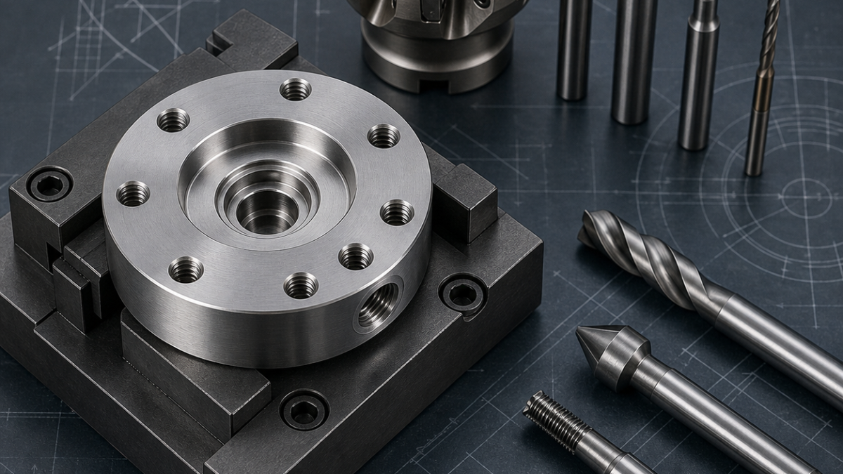
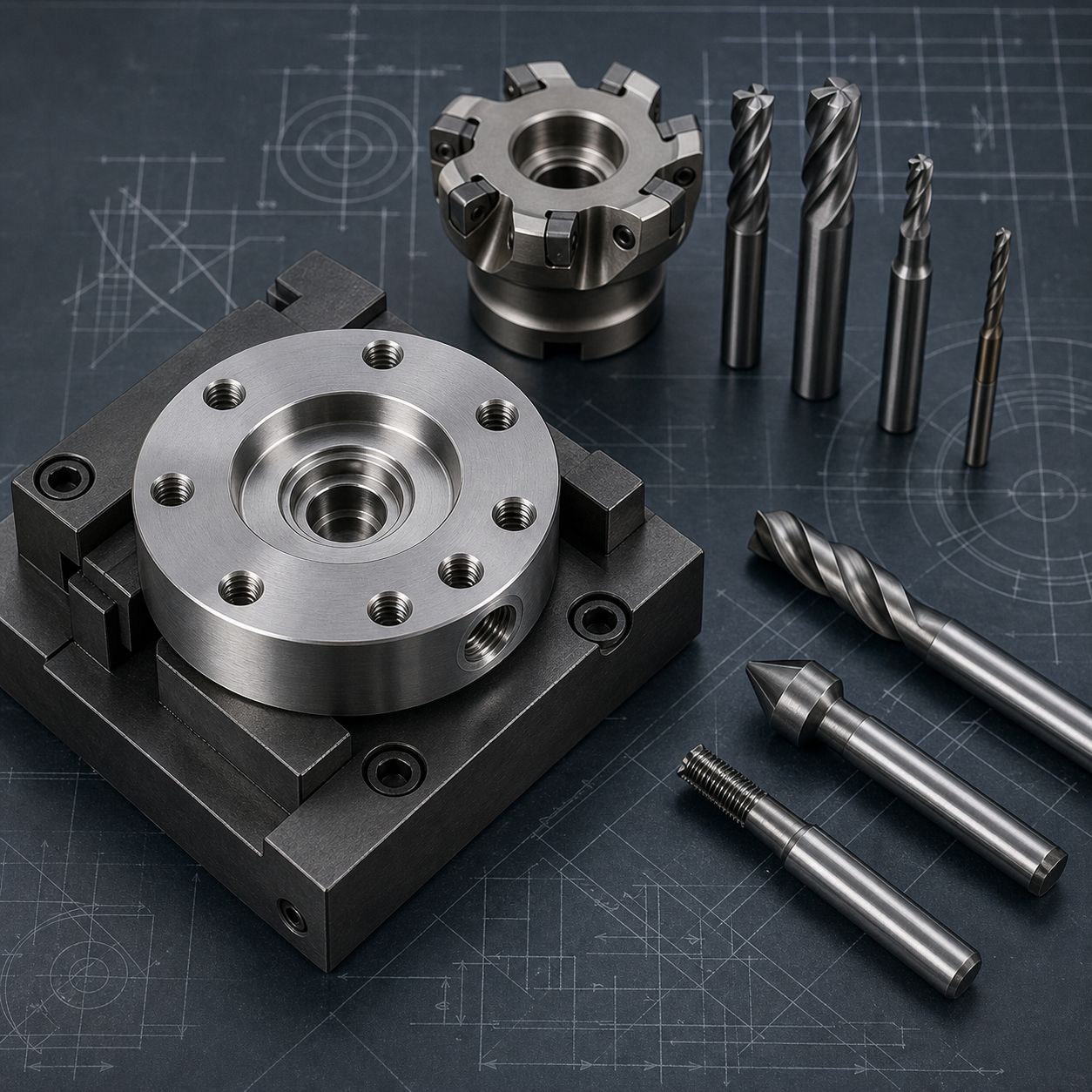
This hypothetical case starts with a 15-5PH stainless pressure-sensor flange made from solution-treated stock. The drawing calls for a central stepped bore, a shallow rear diaphragm pocket, a circular sealing land, a bolt circle, one radial pressure port and controlled flatness between the mounting and sealing faces. The manufacturing risk is not simply material removal: the thin diaphragm can move after roughing, while the sealing land must remain clean and concentric to the functional bore.
Datum and fixture plan
Use the broad mounting face as primary datum A, the stepped bore as datum B and one bolt-circle feature as clocking datum C. Rough the blank in soft jaws, leaving balanced stock on both faces. After stress is released, finish the bore and sealing face in one clamping. For the reverse operation, use a relieved nest that supports the flange rim without loading the diaphragm area.
Tool-to-feature selection
- A positive-rake carbide face mill establishes datum A with low axial force.
- A variable-helix carbide end mill roughs the diaphragm cavity with constant engagement and a conservative axial step.
- A short-reach corner-radius end mill semi-finishes the pocket; a fresh sharp finisher leaves the final diaphragm thickness.
- A pilot drill followed by a carbide drill and thread mill produces the radial port while avoiding tap breakage in stainless steel.
- A 90-degree carbide chamfer tool breaks only specified edges and protects the sealing land.
Process sequence and quality control
Rough both sides before final sizing, allow the part to stabilize, then finish the bore, face and sealing land together. Use climb milling, consistent coolant delivery and reduced radial engagement to limit work hardening. Probe the bore position before machining the bolt circle. Inspect diaphragm thickness at several points, face flatness on a controlled support, bore size and port location. Surface finish should be verified on the sealing land, not inferred from tool marks.
Related reading: 17-4PH clevis bracket datum and cross-hole planning and CNC toolpath smoothing for surface finish.
中文:15-5PH压力传感器法兰的图纸解读与刀具方案
本假设案例的关键特征包括台阶孔、薄膜腔、环形密封面、螺栓孔组和径向压力接口。先把安装大平面设为主基准A,以精孔为基准B,再用一个孔位确定角向基准C。粗加工时两面均匀留量,释放内应力后,在同一次装夹中精加工内孔和密封面。
工艺与风险控制
薄膜腔使用变螺旋硬质合金立铣刀恒定负载粗铣,再用短刃圆角刀半精加工,最后用锋利精加工刀控制膜片厚度。径向接口采用引导孔、硬质合金钻头和螺纹铣刀组合,降低不锈钢中断丝锥的风险。反面装夹应支撑外圈,避免夹紧力直接作用在薄壁区。检验重点是膜片多点厚度、密封面平面度、孔径及接口位置。
Français : gamme d’usinage d’une bride capteur en 15-5PH
Ce cas hypothétique concerne une bride avec alésage étagé, poche de membrane mince, portée d’étanchéité, cercle de trous et orifice radial. La grande face devient le datum A, l’alésage le datum B et un trou définit l’orientation C. Il faut ébaucher les deux faces avec une surépaisseur équilibrée, puis finir l’alésage et la portée dans le même serrage.
Outils et maîtrise du risque
Une fraise carbure à hélice variable convient à l’ébauche à engagement constant. Une fraise torique courte réalise la semi-finition et un outil neuf termine la membrane. L’orifice radial est percé puis fileté par interpolation afin de réduire le risque de casse. Le contrôle porte sur l’épaisseur en plusieurs points, la planéité de la portée, le diamètre d’alésage et la position de l’orifice.
Русский: обработка фланца датчика из 15-5PH
В условном примере деталь содержит ступенчатое отверстие, тонкую мембранную полость, уплотнительную поверхность, окружность крепёжных отверстий и радиальный резьбовой канал. Основной базой служит широкая монтажная плоскость, второй базой — точное отверстие, а угловое положение задаёт один из крепёжных элементов.
Инструменты и контроль
Черновую выборку выполняют твердосплавной фрезой с переменным углом спирали и постоянным зацеплением. Короткая радиусная фреза оставляет равномерный припуск, а новая чистовая фреза формирует мембрану. Радиальный канал сверлят и обрабатывают резьбовой фрезой. Проверяют толщину мембраны в нескольких точках, плоскостность уплотнения, диаметр отверстия и координаты канала.
FAQ
Why not finish the diaphragm during the first roughing setup?
Removing the remaining stock can redistribute stress and move the thin section. Balanced roughing followed by a stable finishing setup gives better control.
Why use a thread mill for the radial port?
It reduces cutting load, permits diameter adjustment and is easier to recover from than a broken tap in a high-value stainless part.


