This is a realistic hypothetical process-planning example, not a claim about a specific customer drawing or production result.
Related: Compare thin-feature support in the copper thin-fin case and free-state inspection in the A286 curved clamp case.
English: reading the bulk-metallic-glass flexure drawing
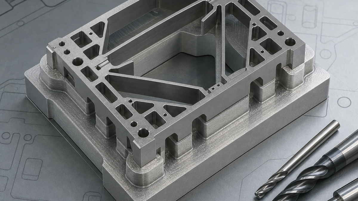
This hypothetical Zr-Cu-Al bulk metallic glass frame contains compliant beams, narrow pockets, pin holes and controlled edge breaks. The material offers high strength but limited tolerance for heat-driven structural change, so the drawing must be converted into a low-heat sequence that preserves the free-state flexure geometry.
Feature, datum and inspection plan
Use the broad outer pads as temporary datums while the center remains supported. Separate functional beam thickness from ordinary pocket dimensions, and identify where profile is inspected in the free state. Pin holes should transfer the coordinate system between roughing, release and final inspection.
Sharp carbide micro-tool package
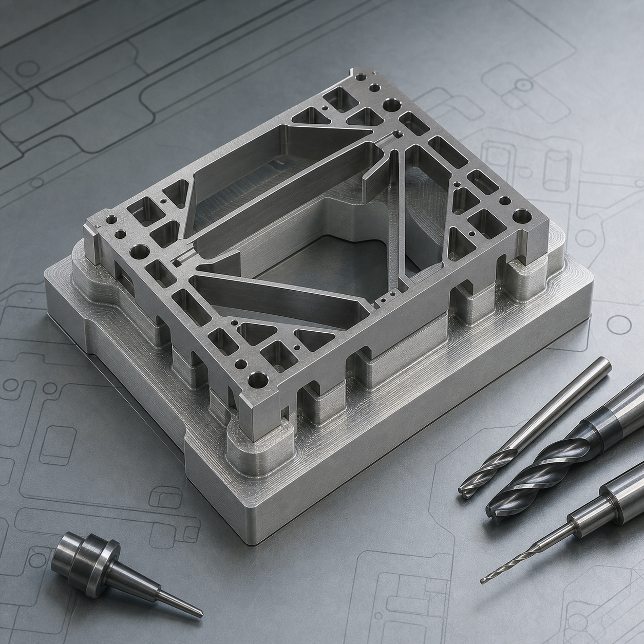
Use a short sharp carbide end mill for rough pockets with low radial engagement, a reduced-neck finisher for beam walls, carbide micro drills followed by a reamer for the pin holes, and a small chamfer tool for controlled edge breaks. Favor polished flutes and minimal edge hone; rubbing adds heat without useful material removal.
Sacrificial fixture and machining sequence
Bond or mechanically retain the blank on a full-contour sacrificial support compatible with the process specification. Rough pockets in alternating zones, keep bridge tabs around each beam, and allow cooling pauses based on measured temperature rather than fixed time. Finish beam walls before releasing tabs, then remove bridges in a balanced pattern with minimal tool engagement.
Thermal, chipping and tool-life risks
The chief risk is localized heating that changes surface condition or amorphous structure; edge chipping and micro-tool runout are also critical. Use high-speed air or approved coolant, verify spindle runout, avoid dwell, and monitor tool diameter through test cuts. Inspect beam width and frame profile only after release and temperature stabilization.
FAQ
Why not remove all pocket material immediately?
The sacrificial web and bridge tabs prevent flexible beams from vibrating or moving while their surfaces are finished.
Can aggressive coolant always be used?
No. Coolant chemistry and thermal shock must match the alloy and downstream cleanliness specification.


