English: Case Overview
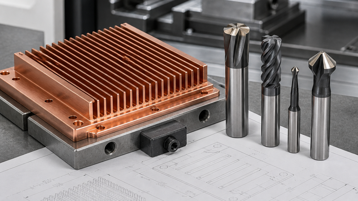
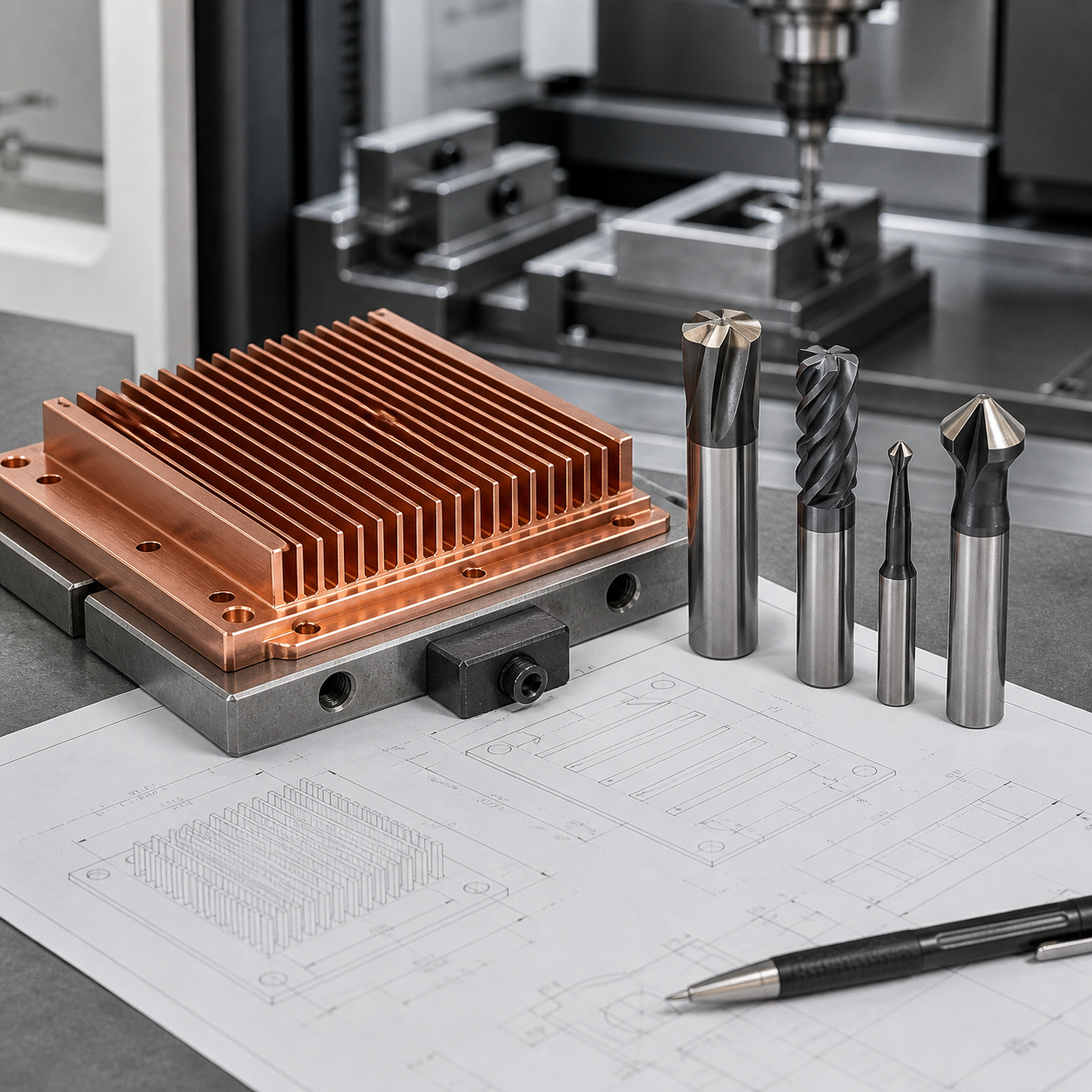
This hypothetical copper alloy heat sink drawing includes thin fins, a flat base, mounting holes and a cosmetic surface requirement. Copper is ductile, so tool sharpness and chip control are central to the CNC tooling solution. The wrong cutter can smear the surface, create built-up edge and bend delicate fins.
A practical tool plan may use a PCD cutter or polished carbide end mill for finishing, a sharp carbide end mill for slotting between fins, carbide drills for mounting holes and a small chamfer tool for edge breaks. The fixture should support the base evenly so flatness is not lost during fin machining.
Process Plan
Rough the heat sink outline first, then machine fin gaps with a sharp tool and controlled chip evacuation. Leave the base finishing pass until after the fin structure is stable. Avoid excessive side pressure on thin fins, and inspect flatness after unclamping.
Machining Takeaway
For copper heat sink machining, a good drawing-based tooling plan protects both thermal surface quality and thin-fin geometry. Sharp tools and stable support are the core of the solution.


