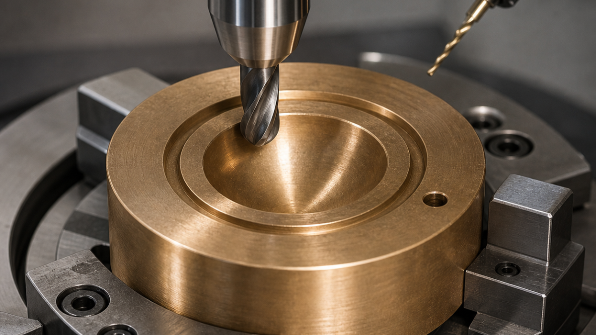
English: C93200 Bronze Slipper Pad CNC Tool Selection for Spherical Socket and Lapping Face
A C93200 hydraulic slipper pad succeeds when the spherical socket, hydrostatic pocket and future lapping face are treated as one geometry chain. Sharp uncoated carbide prevents leaded bronze from smearing, a swept single-point tool finishes the socket without dwelling at the pole, and the sliding face keeps measured lapping stock rather than being polished to final size in the machining centre. This hypothetical case maps every oil feature to a separate low-force tool.
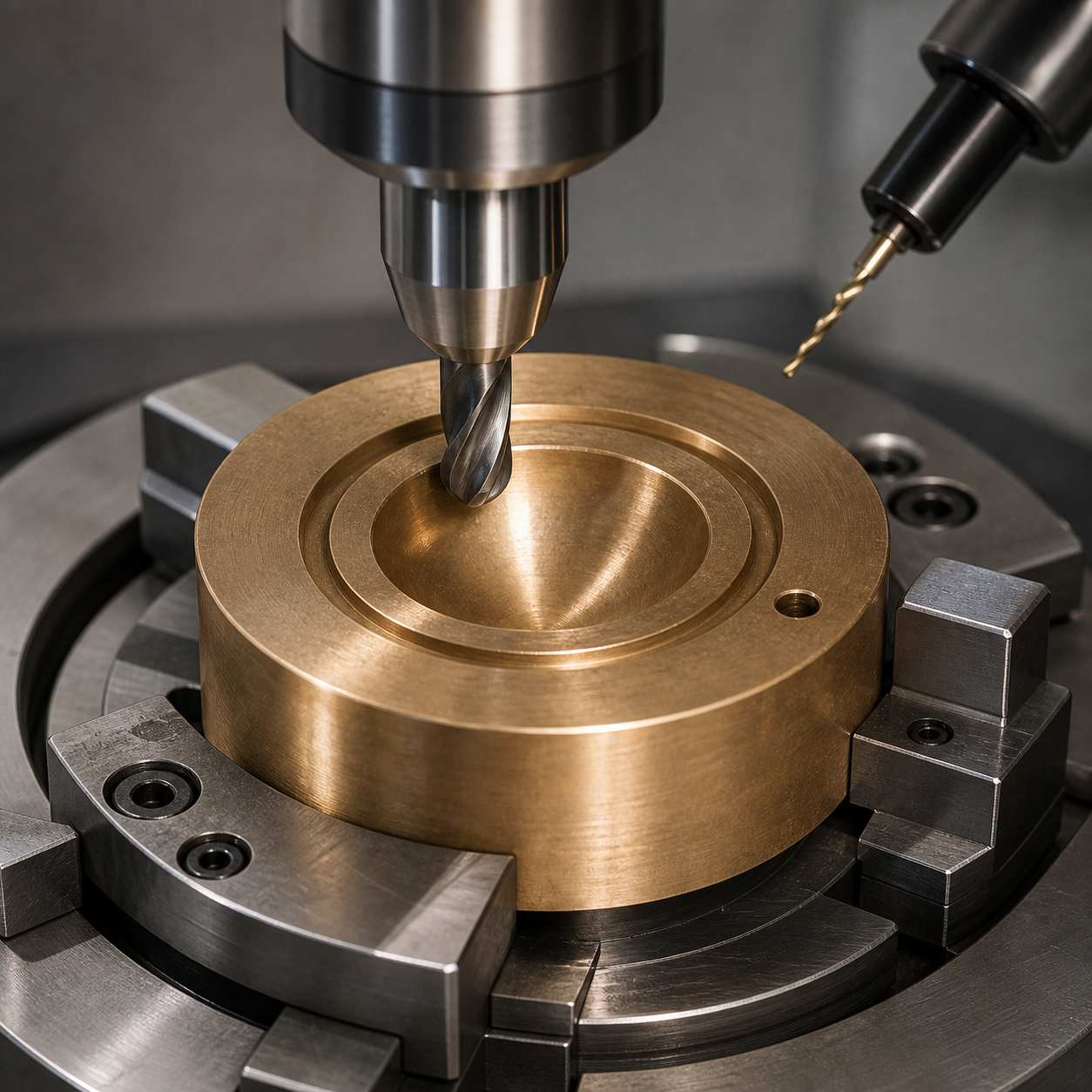
Start from the ball centre, not the outside diameter
The drawing defines spherical socket S as the primary functional feature. Its radius is SR12.50 ±0.010 mm and its centre is 8.00 ±0.015 mm from sliding datum A. Face A has 0.003 mm flatness after lapping and stays parallel to the socket centreline within 0.005 mm. A Ø16.0 hydrostatic pocket is 0.40 mm deep, surrounded by a 1.00 × 0.30 mm annular restrictor groove. A central Ø0.80 +0.010/0 mm metering hole connects the socket to the pocket. The Ø32 h7 outside diameter is only a handling datum, not the origin for socket correction.
Machining therefore leaves 0.015 mm on face A for the separate lapping operation. Removing that stock early would shift the hydraulic gap after the sphere had already been accepted.
Low-force feature-to-tool plan
| Feature | Selected tool, edge and holder | Rationale and alternative rejected |
|---|---|---|
| Blank OD and reference face | Ø12 three-flute uncoated micrograin-carbide end mill, polished 35° helix, R0.3, 0.01 mm edge preparation, hydraulic holder | The positive edge shears the soft matrix; a honed steel-grade tool burnishes lead-rich areas. |
| Spherical socket roughing | Ø8 two-flute uncoated polished-carbide ball mill R4, 14 mm reach, shrink-fit holder | A spiral path leaves 0.12 mm normal stock; excessive flute count traps soft chips. |
| Spherical socket finishing | R0.2 polished uncoated-carbide insert in a swept spherical-boring attachment, positive 18° rake, rigid short cartridge | Maintains cutting speed through the pole; a ball mill rubs near its zero-speed centre. |
| Hydrostatic pocket | Ø6 single-flute O-geometry uncoated carbide, polished face, R0.1, precision collet | Large chip space prevents recutting; a four-flute cutter can pack bronze into the floor. |
| Restrictor groove | Ø1.0 two-flute straight-groove carbide slot mill, polished lands, 1.2 mm cutting length, micro hydraulic chuck | Two compensated circular passes control both walls; a fixed form cutter cannot correct asymmetric wear. |
| Metering orifice | Ø0.76 two-flute carbide drill, 130° split point, internal coolant, followed by Ø0.80 four-flute straight carbide reamer with 0.5 mm short lands | The reamer defines flow diameter; laser drilling is unnecessary and can leave a recast layer in this hypothetical route. |
| Lapping-stock face | Single-edge PCD fly cutter Ø24 sweep, R0.4, balanced arbor, preset to leave 0.015 mm | Produces uniform stock; finish lapping inside the machine would contaminate guides and erase the datum allowance. |
| Oil-edge breaks | Ø3 single-flute polished carbide 90° chamfer tool, 0.05 mm break | A brush could roll bronze into the Ø0.80 orifice. |
Two nests and a controlled lapping allowance
Operation one holds the blank on three broad soft pads and establishes the outside diameter, back face and rough socket. A helical ramp keeps the ball mill moving, and filtered coolant carries chips away from the spherical floor. After probing the rough sphere, the swept boring attachment finishes from mouth to pole in one continuous arc; it never pauses at the centre.
Operation two locates on a qualified master-ball nest with a light axial clamp outside the future sliding band. The pocket, groove and metering hole are now positioned from S rather than from the OD. The fly cutter then creates uniform lapping stock on A. A waxy smear, intermittent torque rise or an orifice exit lip indicates a dull edge. Abrasive lapping occurs in a separate area, followed by ultrasonic cleaning compatible with the specified bronze and hydraulic service.
Inspection tied to hydraulic function
A calibrated sphere and contact scan verify socket radius, form and centre height. Before lapping, a CMM checks the pocket and groove relative to S; after lapping, an optical flat or qualified interferometric method checks A flatness. A profile trace measures groove width and depth. The metering hole is verified by pin and a controlled flow test, because diameter alone will not reveal a partial burr.
What cutter should finish a bronze slipper socket?
A positive polished carbide single-point edge swept around the sphere avoids the near-zero cutting speed at the centre of a ball end mill.
Why leave stock for lapping the slipper face?
The separate lapping step produces the functional flatness; machining to final thickness first would move the hydraulic gap when that stock is removed.
How is a 0.8 mm metering hole protected from burrs?
Use a short drill-and-ream sequence, support the exit, add a 0.05 mm programmed break and verify actual flow after cleaning.
Related cases: bronze bearing bore and oil-groove tooling and functional contact-surface finishing.
中文: C93200青铜滑靴CNC配刀:球窝、节流孔与研磨面
C93200液压滑靴的配刀中心不是外圆,而是球窝中心S。球窝、静压油腔、环形节流槽和最终研磨面必须在同一尺寸链中完成。锋利无涂层硬质合金避免含铅青铜涂抹,摆动式单刃精加工球窝,滑动面则保留明确研磨余量,不能在机床里直接“抛到尺寸”。
功能尺寸链
球窝SR12.50 ±0.010 mm,其中心到滑动基准A为8.00 ±0.015 mm;A面研磨后平面度0.003 mm,对球窝中心线平行0.005 mm。Ø16静压腔深0.40 mm,外围是1.00×0.30 mm节流槽,中央Ø0.80 +0.010/0 mm量孔连通球窝。Ø32 h7外圆只用于搬运定位,不能代替S修正油腔。
低切削力配刀矩阵
| 加工区 | 刀具配置 | 为什么这样选 |
|---|---|---|
| 外圆和参考面 | Ø12三刃无涂层细晶硬质合金,35°抛光槽,R0.3,刃口0.01 mm,液压刀柄 | 正前角剪切软基体,钢件钝化刀会压亮含铅区。 |
| 球窝开粗 | Ø8双刃无涂层抛光硬质合金球刀R4,悬伸14 mm,热缩刀柄 | 螺旋刀路法向留0.12 mm,大容屑槽防止软屑堵塞。 |
| 球窝精加工 | R0.2抛光无涂层硬质合金刀片,18°正前角,摆动球面镗削附件,短刀匣 | 刀尖越过球极仍有切削速度;球刀中心容易擦伤。 |
| 静压油腔 | Ø6单刃O刃无涂层硬质合金,抛光前刀面,R0.1,精密筒夹 | 大排屑空间防止青铜屑二次压入底面。 |
| 节流槽 | Ø1.0双刃抛光直槽硬质合金刀,刃长1.2 mm,微型液压刀柄 | 两圈补偿两侧,成形刀不能分别修磨损。 |
| Ø0.80量孔 | Ø0.76双刃内冷硬质合金钻,130°分割刃,再用Ø0.80四刃短刃直槽硬质合金铰刀 | 铰刀确定流量孔径,避免激光重铸层。 |
| A面研磨余量 | Ø24扫掠单刃PCD飞刀,R0.4,平衡刀杆,保留0.015 mm | 留下均匀余量,研磨工序不得污染机床导轨。 |
| 油路倒角 | Ø3单刃抛光硬质合金90°刀,倒0.05 mm | 刷子可能把软青铜卷入小孔。 |
以球心换基准
第一序用三块宽软垫支承,建立外圆、背面并开粗球窝。球刀连续螺旋,不在球底停顿;探测粗球后,摆动单刃从口部连续扫到球极完成精加工。第二序使用合格标准球座定位S,低轴向力压在滑动带之外,然后从球心加工油腔、节流槽和量孔。
PCD飞刀给A面留下0.015 mm均匀研磨量。蜡状涂抹、扭矩跳变或量孔出口翻边都触发换刀。研磨必须在独立区域完成,之后按液压清洁要求去除所有磨粒。
检验与搜索问题
标准球与接触扫描测球窝半径、形状及中心高;研磨前由三坐标测油腔和槽对S的位置,研磨后用光学平晶或合格干涉方法测A面。轮廓仪测槽宽深,量孔既用针规,也做受控流量测试。
青铜滑靴球窝用什么刀精加工?
采用正前角抛光硬质合金单刃摆动加工,避免球刀中心在球极零速摩擦。
为什么滑动面必须留研磨量?
功能平面度来自独立研磨;若机加工先到最终厚度,研磨会改变液压间隙。
0.8 mm节流孔怎样防堵?
短钻加短刃铰刀、出口支承、程序倒0.05 mm,并在清洗后做流量验证。
参考:青铜轴套孔与油槽配刀、功能接触面的精加工。
Français: Choix d’outils CNC pour patin C93200 : rotule, orifice et face rodée
Le centre de la rotule S gouverne ce patin hydraulique, pas son diamètre extérieur. Un carbure non revêtu et poli coupe le bronze plombé sans l’étaler; un outil monopointe balayé termine la sphère; la face de glissement conserve 0,015 mm pour un rodage séparé.
Chaîne fonctionnelle du plan
La rotule SR12,50 ±0,010 mm place son centre à 8,00 ±0,015 mm de A. Après rodage, A doit être plane à 0,003 mm et parallèle à l’axe de S à 0,005 mm. La poche hydrostatique Ø16 a 0,40 mm de profondeur, la gorge fait 1,00×0,30 mm et l’orifice central Ø0,80 +0,010/0 mm.
Sélection par fonction
| Fonction | Outil et maintien | Choix |
|---|---|---|
| Références | Ø12, trois dents carbure non revêtu, hélice polie 35°, R0,3, arête 0,01 mm, hydraulique | Coupe la matrice sans brunissage. |
| Ébauche sphère | Boule Ø8 R4, deux dents polies, portée 14 mm, frettage | Grand espace pour les copeaux. |
| Finition sphère | Plaquette carbure polie R0,2, angle positif 18°, tête d’alésage sphérique balayée | Conserve une vitesse au pôle. |
| Poche | Ø6, une dent O, carbure poli, R0,1 | Évite la recoupe des copeaux. |
| Gorge | Ø1,0, deux dents droites polies, coupe 1,2 mm | Deux parois compensables. |
| Orifice | Foret Ø0,76 arrosé à 130°, puis alésoir carbure Ø0,80 à quatre goujures courtes | Le calibre correspond au débit. |
| Stock de rodage | Monodent PCD, balayage Ø24, R0,4, arbre équilibré | Laisse 0,015 mm uniforme. |
| Cassés | Carbure poli Ø3, une dent, 90°, 0,05 mm | Ne roule pas le bronze dans l’orifice. |
Deux montages et contrôle du débit
Le premier nid établit les références et la sphère. L’outil balayé va de la bouche au pôle sans arrêt. Le second nid s’appuie sur une bille étalon et place poche, gorge et orifice depuis S. La face reçoit ensuite son stock de rodage. Toute trace cireuse ou lèvre à la sortie impose le changement de l’arête.
Le contact sur bille contrôle la sphère; la MMT mesure les fonctions avant rodage; un plan optique vérifie A après rodage. Le profilomètre mesure la gorge et un essai de débit complète la pige de l’orifice.
Quel outil pour la rotule?
Une monopointe carbure positive et polie, balayée autour du centre.
Pourquoi garder du stock de rodage?
Parce que le rodage produit la planéité hydraulique finale.
Comment sécuriser l’orifice?
Perçage court, alésage, cassé de 0,05 mm et mesure de débit.
Comparer la douille en bronze et la surface de contact Stellite.
Русский: Инструмент для башмака C93200: сфера, дроссель и притирка
У гидравлического башмака базой служит центр сферы S, а не наружный диаметр. Полированный карбид без покрытия режет свинцовую бронзу без размазывания, однолезвийная расточка проходит сферу без остановки в полюсе, а на рабочей плоскости остаётся 0,015 мм под отдельную притирку.
Функциональные размеры
Радиус SR12,50 ±0,010 мм расположен на 8,00 ±0,015 мм от A. После притирки плоскостность A равна 0,003 мм, параллельность оси S — 0,005 мм. Гидростатический карман Ø16 имеет глубину 0,40 мм, канавка — 1,00×0,30 мм, центральное отверстие — Ø0,80 +0,010/0 мм.
Таблица инструмента
| Операция | Инструмент | Обоснование |
|---|---|---|
| Базы | Ø12, три зуба, полированный карбид без покрытия, 35°, R0,3, кромка 0,01 мм, гидропатрон | Не накатывает мягкую матрицу. |
| Черновая сфера | Шаровая Ø8 R4, два полированных зуба, вылет 14 мм | Место для мягкой стружки. |
| Чистовая сфера | R0,2, положительная полированная карбидная пластина 18° в сферической расточной головке | Режет и в полюсе. |
| Карман | Ø6, один O-зуб, полированный карбид, R0,1 | Не вдавливает стружку. |
| Канавка | Ø1,0, два прямых зуба, длина 1,2 мм | Стенки корректируются отдельно. |
| Дроссель | Сверло Ø0,76 с внутренней СОЖ, 130°, затем короткая развёртка Ø0,80 | Размер связан с расходом. |
| Припуск A | Однозубый PCD, проход Ø24, R0,4, сбалансированная оправка | Оставляет 0,015 мм равномерно. |
| Фаски | Ø3, один полированный зуб, 90°, 0,05 мм | Не завальцовывает дроссель. |
Установки и измерение
Первая установка создаёт базы и сферу; расточная кромка непрерывно идёт от входа к полюсу. Вторая опирается на эталонный шар и размещает карман, канавку и отверстие от S. Затем PCD оставляет припуск для притирки. Восковой след, скачок момента или выходная кромка означают смену инструмента.
Эталонная сфера и сканирование проверяют форму, КИМ — расположение гидравлических элементов. После притирки оптическая плоскость проверяет A; профиль и расход подтверждают канавку и отверстие.
Чем закончить сферу?
Положительной полированной карбидной кромкой в сферической расточной головке.
Зачем припуск на притирку?
Именно притирка создаёт окончательную гидравлическую плоскость.
Как защитить отверстие Ø0,8?
Коротким сверлением, развёрткой, фаской 0,05 мм и проверкой расхода.
Связанные примеры: бронзовая втулка и контактная поверхность Stellite.


