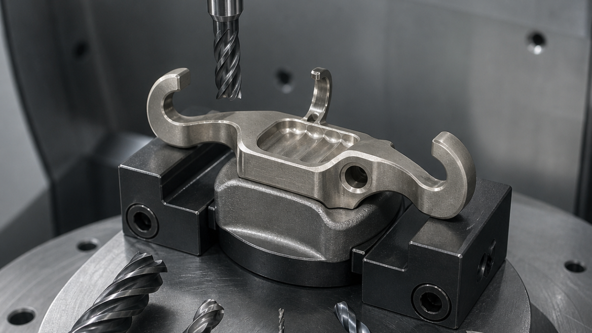
English: Nimonic 90 Turbine Damper CNC Tooling Case: Curved Contact Pads and Thin Hook
A Nimonic 90 under-platform damper needs its tooling budget spent on contact geometry, not bulk stock. A tough Ø10 coated carbide cutter opens the forging, a Ø6 bull nose establishes uniform stock on two curved pads, and a necked Ø3 finisher reaches the thin hook without forcing it. The angled hole and edge breaks receive separate tools so work-hardened material is never rubbed twice.
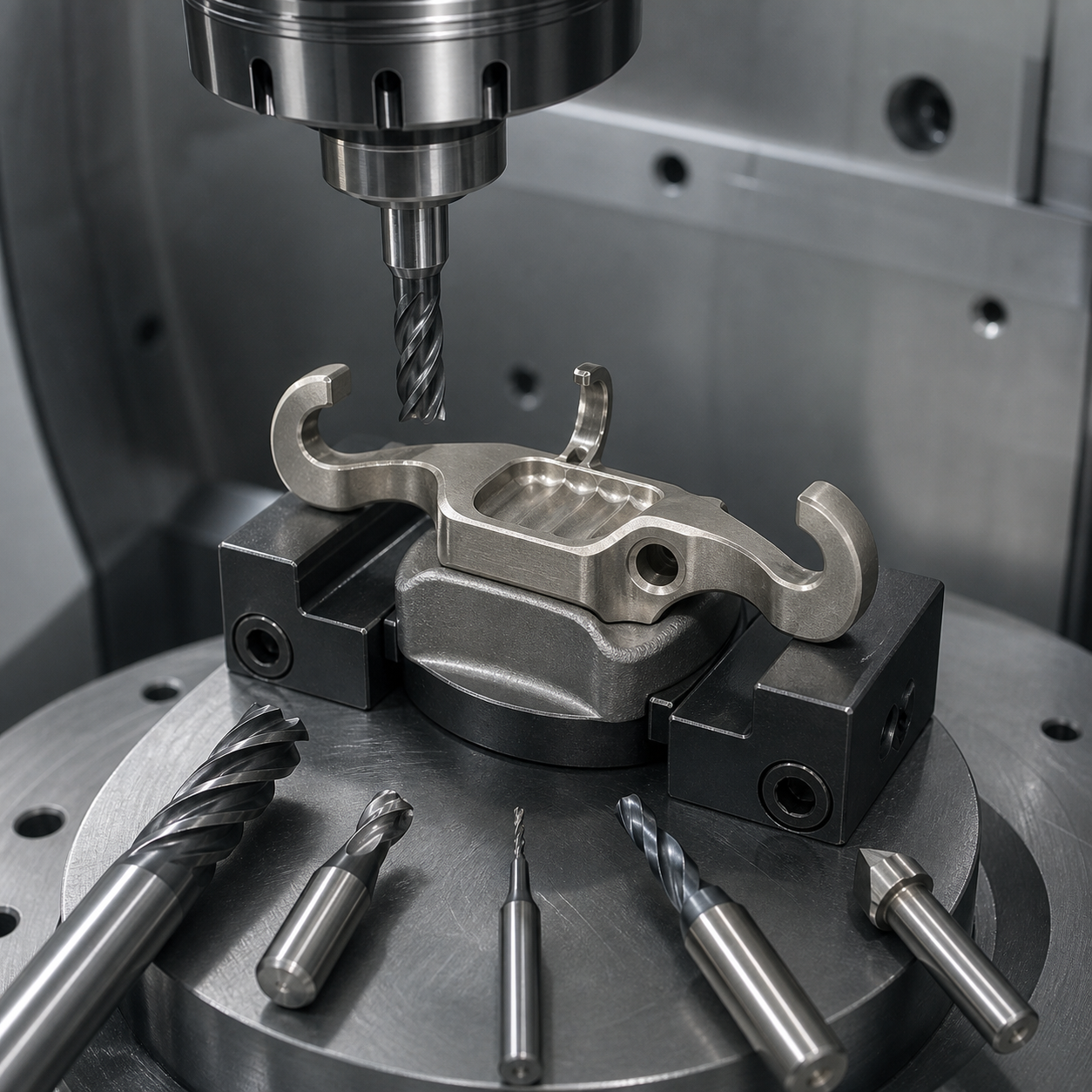
Accessibility map from the drawing
Contact pad A seats against one blade platform; pad B is profile-controlled 0.025 mm to A and an angled Ø3 hole defines C. The hook is 2.10 ±0.05 mm thick, its root is R1.5 minimum, the relief pocket stops 0.30 mm from the contact envelope, and both pads require Ra 0.8 µm. Only three tool vectors can reach the underside without holder collision, so reach and shank clearance are part of the tolerance plan.
Tool assignments and life budget
| Cutting zone | Carbide tool, geometry and holder | Planned duty |
|---|---|---|
| Forged skin | Ø10 five-flute variable-pitch AlTiN micrograin carbide, 0.08 mm hone, R0.5, hydraulic holder | Adaptive roughing below 12% radial engagement; one edge set is reserved for skin only. |
| Curved pads semifinish | Ø6 five-flute TiAlN bull nose R0.5, 20 mm reach, shrink holder | Constant-cusp passes leave 0.18 mm normal stock on A and B. |
| Pad finish | Ø4 six-flute AlCrN ball nose R2, polished flute, 14 mm reach, high-accuracy shrink holder | Parallel-to-contact finishing with runout below 0.005 mm. |
| Thin hook and root | Ø3 four-flute AlTiN necked end mill R0.3, 28 mm reach, hydraulic micro chuck | Alternating hook faces in 0.4 mm axial bands; tool never removes bulk stock. |
| Scalloped relief | Ø5 four-flute chip-splitter carbide, AlTiN, 18 mm reach | Short trochoidal arcs keep chip thickness above rubbing range. |
| Angled Ø3 hole | Ø2.9 through-coolant solid-carbide drill, 140° point, reinforced margin, followed by Ø2 back-chamfer tool | One continuous feed after spot location; internal exit receives a measured break. |
| External edges | Ø6 four-flute AlTiN 90° chamfer mill, minimum projection | Creates 0.10 mm edges before the final pad pass. |
A ceramic cutter was considered for the open pad but rejected because the damper never offers a long continuous engagement; frequent entry, the forged-skin transition and the thin hook make tough coated carbide more predictable. A long ball nose was also rejected: it reaches the underside but adds compliance where the contact profile is most sensitive.
Five-axis fixture and cutting order
A contoured soft nest supports both future pads while two low clamps act on sacrificial forging tabs. The Ø10 tool opens the central relief and leaves the hooks joined by temporary bridges. Pad A is semifinished, the part is indexed, and pad B is brought to equal normal stock. Only then are bridges reduced and the hook faces alternated. Tool-axis smoothing limits rotary acceleration near the root; every finish path exits onto noncontact material.
High-pressure coolant remains directed at the active flute. Notch wear at the depth line, a brown heat tint, spindle-load slope and profile drift between pad scans form the tool-change rule. Feed is maintained through corners by lead/tilt and path-radius control; dwell or repeated spring passes would work-harden Nimonic 90. Chips are kept short and removed from the nest before indexing.
Inspection and FAQ
A CMM builds A-B-C in the nest and scans both pads on a common mesh. An optical system measures hook thickness and root radius without probe deflection; a borescope checks the angled-hole exit. Surface finish follows the pad contact direction. After unclamping, a free-state scan distinguishes fixture release from cutter error, and a qualified contact master checks seating only after geometry passes.
Which carbide end mill should rough Nimonic 90?
A tough variable-pitch five-flute AlTiN micrograin cutter with reinforced edge and controlled radial engagement is suitable here; the skin tool is not reused for finishing.
How is a thin turbine-damper hook finished without bending it?
Leave temporary support, use a necked Ø3 tool only for residual stock, alternate both faces in small axial bands and remove bridges late.
Why not use ceramic for the curved contact pads?
The engagement is short and repeatedly interrupted; carbide tolerates entry and changing contact more reliably in this hypothetical route.
Compare five-axis nickel-alloy tool-life control and tool choice under interrupted hard-alloy contact.
中文: Nimonic 90涡轮减振块配刀:曲面接触垫与薄钩
Nimonic 90叶下减振块的刀具寿命应优先留给接触几何,而不是大余量。Ø10韧性涂层刀开锻造皮,Ø6牛鼻刀均化两块曲面余量,缩颈Ø3刀只精薄钩;斜孔和边缘各用专刀,避免在加工硬化层上重复摩擦。
图纸可达性
A接触垫与叶片平台配合,B垫对A轮廓度0.025 mm,Ø3斜孔定义C。薄钩厚2.10 ±0.05 mm、根部最小R1.5,减重腔距接触包络0.30 mm,两垫Ra 0.8 µm。钩底只有三个无碰撞刀轴方向,因此刀具悬伸和刀柄外形属于公差方案。
刀具与寿命预算表
| 区域 | 刀具、几何和刀柄 | 任务 |
|---|---|---|
| 锻造皮 | Ø10五刃变齿AlTiN微粒硬质合金,0.08 mm强化刃,R0.5,液压刀柄 | 径向吃刀低于12%,此刃口只用于锻皮。 |
| 曲面半精 | Ø6五刃TiAlN牛鼻刀R0.5,悬伸20 mm,热缩刀柄 | 等残高后对A、B各留法向0.18 mm。 |
| 垫面精加工 | Ø4六刃AlCrN球刀R2,抛光槽,悬伸14 mm,高精热缩 | 沿接触方向平行精刀,跳动小于0.005 mm。 |
| 薄钩 | Ø3四刃AlTiN缩颈刀R0.3,悬伸28 mm,液压微夹头 | 两面按0.4 mm轴向带交替,只清余量。 |
| 减重腔 | Ø5四刃AlTiN分屑刀,悬伸18 mm | 短摆线圆弧保持有效切屑厚度。 |
| Ø3斜孔 | Ø2.9内冷整体硬质合金钻,140°强化刃带+Ø2反向倒角刀 | 点定位后连续进给,内口定量倒钝。 |
| 外边 | Ø6四刃AlTiN 90°倒角刀,短悬伸 | 最终接触面前完成0.10 mm边缘。 |
曾考虑用陶瓷刀加工开放垫面,但该零件没有长时间连续接触,锻皮过渡、频繁进出和薄钩更适合韧性涂层硬质合金。长悬伸球刀虽然可达,却会在最敏感的接触区增加弹性,因此同样排除。
五轴装夹与刀路
随形软座支承未来两块垫面,低压夹块只压牺牲锻造耳。先开中央腔并保留连接薄钩的临时桥;A、B分别半精到等量法向余量后,才减薄连接桥并交替加工钩两面。刀轴平滑限制根部转轴加速度,精刀始终退出到非接触区。
高压冷却对准有效刃。深度线沟槽磨损、棕色热斑、负载斜率和两垫扫描漂移共同决定换刀;不允许停顿或无依据弹簧刀造成加工硬化。
检验与问题
三坐标在夹具中建立A-B-C并用同一网格扫描两垫,光学系统无接触测薄钩厚度和R1.5,内窥检查斜孔出口。松夹后再自由扫描,区分夹具回弹与刀具误差。
Nimonic 90开粗选什么刀?
强化刃的五刃变齿AlTiN细晶刀配小径向吃刀量,且锻皮刀不转作精刀。
薄钩怎样避免变形?
晚拆临时支承,Ø3缩颈刀只清余量,并按小轴向带交替两面。
为何不用陶瓷刀?
本例频繁断续进出,韧性涂层硬质合金更可控。
Français: Amortisseur Nimonic 90 : patins courbes et crochet mince
La durée de vie est réservée aux contacts: Ø10 ouvre la forge, une torique Ø6 uniformise les patins et une Ø3 dégagée finit le crochet sans enlever le volume principal.
Tableau zone–outil
| Zone | Outil | Mission |
|---|---|---|
| Peau | Ø10, cinq dents variables AlTiN, honage 0,08 mm, R0,5 | Ébauche sous 12% radial. |
| Patins semi-finis | Torique Ø6, cinq dents TiAlN, R0,5, portée 20 mm | Laisse 0,18 mm normal. |
| Patins finis | Boule Ø4, six dents AlCrN, R2, portée 14 mm | Faux-rond sous 0,005 mm. |
| Crochet | Ø3, quatre dents AlTiN, R0,3, col 28 mm | Bandes alternées de 0,4 mm. |
| Relief | Ø5, quatre dents brise-copeaux | Arcs trochoïdaux courts. |
| Trou | Foret Ø2,9 arrosé à 140° puis retour Ø2 | Sortie mesurée. |
| Arêtes | Chanfrein AlTiN Ø6 à 90° | Cassé 0,10 mm. |
La céramique est refusée car l’engagement reste court et interrompu. Le long outil boule est également exclu pour sa flexion.
Montage et contrôle
Un nid souple soutient les deux patins et les brides portent sur des oreilles sacrificielles. Des ponts temporaires restent jusqu’à la finition alternée du crochet. L’arrosage haute pression, l’usure en entaille, la teinte et la dérive de profil pilotent le changement.
La MMT scanne les deux patins; l’optique mesure crochet et rayon, la caméra le trou.
Quelle fraise d’ébauche?
Ø10 AlTiN à cinq dents variables.
Comment soutenir le crochet?
Ponts tardifs et bandes alternées avec Ø3.
Pourquoi pas la céramique?
Contact trop interrompu.
Voir le fraisage nickel cinq axes et la coupe interrompue.
Русский: Демпфер Nimonic 90: контактные площадки и крюк
Ресурс направлен на контакты: Ø10 открывает поковку, тороидальная Ø6 выравнивает площадки, шейковая Ø3 заканчивает крюк без съёма большого объёма.
Таблица зона–инструмент
| Зона | Инструмент | Задача |
|---|---|---|
| Корка | Ø10, пять переменных зубьев AlTiN, кромка 0,08 мм, R0,5 | Радиальное зацепление ниже 12%. |
| Полуфиниш | Тороидальная Ø6, пять зубьев TiAlN, R0,5 | Припуск 0,18 мм. |
| Финиш | Шаровая Ø4, шесть зубьев AlCrN, R2 | Биение менее 0,005 мм. |
| Крюк | Ø3, четыре зуба AlTiN, R0,3, шейка 28 мм | Чередование полос 0,4 мм. |
| Карман | Ø5 с делителем стружки | Короткие трохоиды. |
| Отверстие | Карбид Ø2,9, 140°, затем обратная Ø2 | Контроль выхода. |
| Кромки | AlTiN Ø6, 90° | Фаска 0,10 мм. |
Керамика исключена из-за короткого прерывистого контакта, длинная шаровая фреза — из-за прогиба.
Опора и проверка
Мягкое гнездо поддерживает площадки, зажимы стоят на жертвенных ушах. Перемычки удаляют поздно, крюк обрабатывают попеременно. Давление СОЖ, канавочный износ, цвет и дрейф профиля задают смену.
КИМ сканирует площадки, оптика проверяет крюк и радиус, камера — отверстие.
Какая черновая?
Ø10 AlTiN с пятью переменными зубьями.
Как поддержать крюк?
Поздними перемычками и чередованием Ø3.
Почему не керамика?
Слишком прерывистый контакт.


