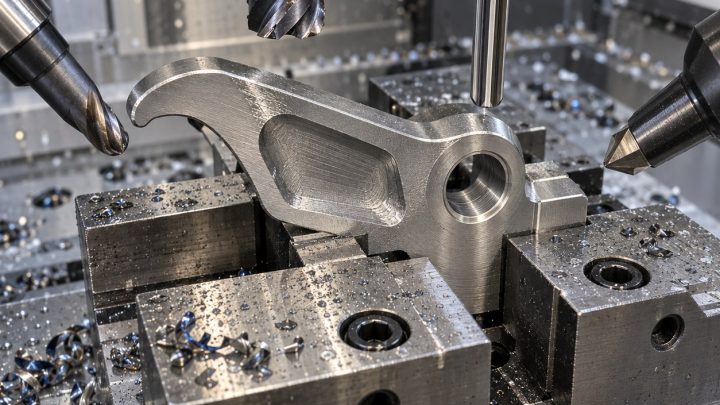
English: Maraging 300 Flexspline Cup CNC Tooling Case: Thin Wall, Spline Preform and Aging Stock
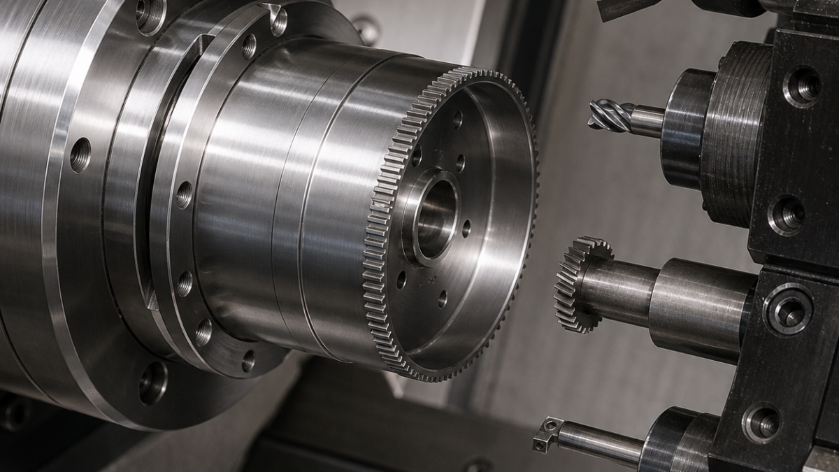
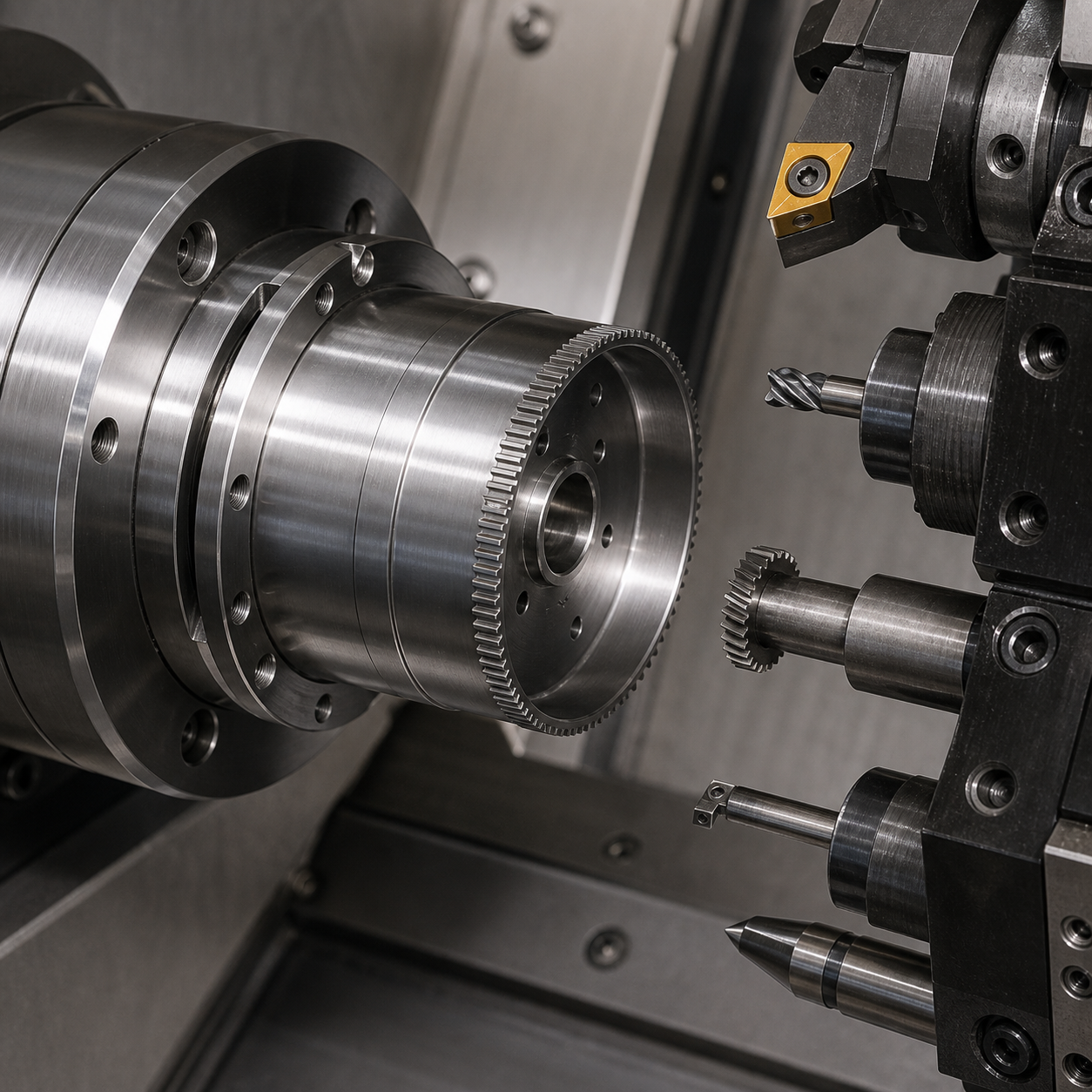
A Maraging 300 flexspline cup needs a tooling plan that anticipates aging rather than merely surviving soft machining. The cup wall is semifinished with a sharp low-force carbide insert while a close-fitting mandrel carries radial load; the external tooth preform is cut with an AlCrN carbide form cutter; and defined stock remains on the pilot and tooth flanks for restoration after aging. The drawing therefore controls when each tool is allowed to create a final surface.
Separate final features from aging-sensitive features
Pilot bore A and diaphragm face B establish the flexspline axis, while one bolt hole defines C. The cup wall is 1.20 ±0.05 mm, the diaphragm blend is R3.0 ±0.10 mm, wall-to-A runout is 0.020 mm, and the external tooth preform is profile-toleranced 0.035 mm before aging. The route targets 52–54 HRC after the specified aging cycle. The drawing leaves 0.12 mm on the pilot diameter and 0.08 mm per tooth flank for final hard finishing; the diaphragm thickness and bolt pattern are finished before aging because later access would load the compliant cup.
Feature-to-tool and process-state selection
| Feature and state | Selected tool, edge and holder | Why / tool not selected |
|---|---|---|
| Solution-treated blank rough turning | CNMG 120408 P30 fine-grain carbide, PVD TiAlN, 0.08 mm hone, rigid cap-clamp holder | Tough enough for intermittent scale. A sharp finishing geometry would notch before the blank becomes continuous. |
| 1.2 mm wall semifinish | Ground VCGT 160404 positive carbide, thin AlTiN PVD, polished rake, R0.4, damped precision holder | Low radial force protects roundness. A negative wiper insert pushes the wall onto and off the mandrel. |
| R3 diaphragm blend | Ø8 five-flute AlTiN bull-nose end mill R1, variable pitch, short flute, shrink holder | Five-axis contouring controls local thickness. A full R3 form tool would load the complete blend. |
| Pilot bore before aging | Positive micrograin-carbide fine-boring insert R0.2 in a short modular head | Leaves concentric 0.12 mm stock. A reamer cannot intentionally distribute hard-finish allowance. |
| External spline preform | Ø50 solid-carbide involute form cutter, 10 teeth, AlCrN coating, edge hone 0.03 mm, precision arbor | Indexes each space with a rigid flank. A small end mill would accumulate profile and indexing error over the full tooth count. |
| Diaphragm bolt holes | Ø4.8 stub through-coolant carbide drill, 140° point, followed by Ø6 three-flute AlTiN chamfer mill | Short drill limits wander through the thin diaphragm; a combined drill-chamfer risks breakout tearing. |
| Post-aging pilot restoration | CBN-tipped fine-boring cartridge R0.2, balanced head, measured wear offset | Holds size in 52–54 HRC material. Coated carbide wear would vary along the interrupted entry. |
| Post-aging tooth flanks | Qualified carbide power-skiving or profile-grinding handoff, selected from distortion map | Only a measured distortion study decides the final method; repeating the soft-state form cut would copy aging error. |
Support strategy and alternating stock removal
The blank is rough-turned as a thick cup and stress-relieved before the wall is released. A ground expanding mandrel contacts the pilot, while a removable backup sleeve supports the wall to within 4 mm of the active cut. Inner and outer diameters are semifinished in alternating 25 mm axial bands so no long unsupported membrane is created. The sleeve is retracted only for the final low-force pass, and wall thickness is verified ultrasonically before tooth machining.
The form cutter machines diametrically opposite tooth spaces in a balanced index sequence. Chip evacuation is directed away from the thin rim, and cutter runout is checked before a profile offset is entered. Rising wall ovality, a repeating tooth-thickness wave or a bright rub band signals mandrel pressure, cutter runout or a dull edge respectively. After aging in a support fixture, free-state roundness and the actual distortion harmonic determine the pilot and tooth-flank finishing offsets.
Inspection and FAQ for flexspline tooling
An air gauge and roundness instrument measure A before and after aging. A CMM checks B-C, diaphragm blend and bolt pattern with the cup supported only at its pilot. A gear measurement system reports tooth thickness, lead and profile around the full circumference; data are Fourier-reviewed to separate indexing error from two-lobe aging distortion. Wall thickness is mapped ultrasonically, then a low-force functional wave-generator check is performed only after dimensional acceptance.
Which insert should turn a 1.2 mm Maraging 300 cup wall?
A ground positive VCGT-style carbide insert with a polished rake, small nose radius and thin PVD coating minimizes radial force; the support mandrel remains equally important.
How much spline stock should remain before aging?
The amount must come from the drawing and qualified distortion study; this hypothetical route leaves 0.08 mm per flank rather than claiming a universal value.
Why not finish the flexspline teeth before aging?
Aging can introduce ovality and harmonic profile change. Measured stock permits the final flanks to be restored from the hardened pilot axis.
Related datum handoffs appear in a carburized spline preform case and the thin-cup support choices in a deep-bore heat-shield cup.