English: RB-SiC Wafer Edge-Grip Ring Diamond Tooling for Datum Pads and Relief Slots
For this hypothetical reaction-bonded silicon carbide ring, the search intent is not simply how to cut SiC. It is how to finish three coplanar datum pads and release narrow compliant fingers without turning a subsurface flaw into a late edge chip. Post-infiltration stock, force direction and coolant cleanliness therefore determine the tool list.
Rank drawing features by fracture consequence
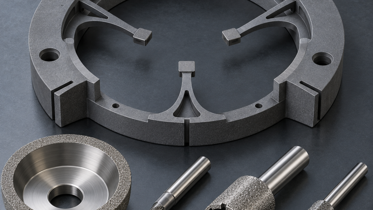
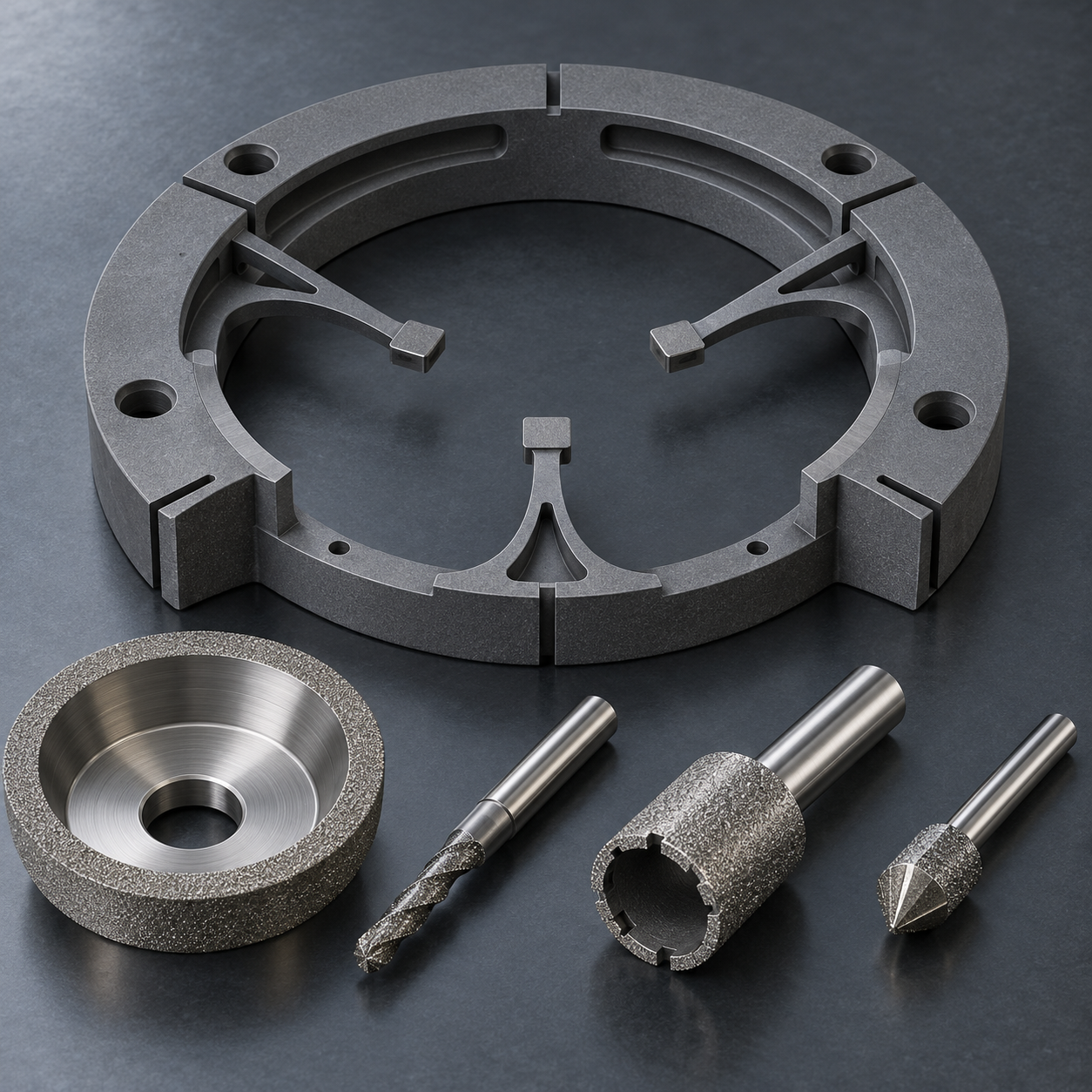
The 180 mm ring has three 1.6 mm-root edge fingers, three datum pads, 0.8 mm radial relief slots, shallow vacuum channels and six mounting bores. The hypothetical drawing sets pad flatness at 0.008 mm, ring runout at 0.015 mm and pad finish at Ra 0.20 micrometre. The finger roots and slot exits are red-risk features; the broad outer rim is green-risk. Inspection points and allowable edge chips must be defined on the drawing rather than improvised at deburring.
Establish the datum before releasing the fingers
The infiltrated near-net blank sits on a full annular vacuum nest with three hard stops and a compliant protective film outside the grinding zone. Rough the back face and outer rim with a D76 metal-bond diamond wheel, then finish the three pads together with a D15 resin-bond cup wheel using spark-out passes. A carbide face mill is rejected because RB-SiC fracture and abrasive wear do not produce a stable cutting edge.
Risk-based diamond tool map for the RB-SiC ring
| Drawing feature | Specified tool, geometry and holder | Why it fits / rejected alternative |
|---|---|---|
| Back face and outer rim | D76 metal-bond diamond wheel, rigid spindle | Efficient stock removal; carbide milling wears and fractures unpredictably. |
| Three datum pads | D15 resin-bond diamond cup wheel with spark-out | Low subsurface damage and shared plane; separate spot grinding risks height mismatch. |
| 0.8 mm relief slots | Fine electroplated diamond slitting wheel with backing support | Directs force into the rim; free-end slotting bends the finger. |
| Radiused slot termination | Small electroplated diamond end mill, minimum projection | Generates the root radius; a sharp wheel corner concentrates stress. |
| Vacuum channels | 2 mm diamond rotary tool, light constant-engagement passes | Controls silicon loading; a deep single pass chips channel edges. |
| Mounting bores and edge break | 6 mm diamond core drill plus fine diamond chamfer point | Supported breakthrough limits exit chips; twist drills are unsuitable. |
Open slots from supported material
Machine each 0.8 mm relief slot with a fine electroplated diamond slitting wheel, entering from the rigid rim and stopping before the finger root. Rotate the fixture and complete the final ligament while a sacrificial ceramic-backed insert supports the finger. A small diamond end mill is used only for the radiused termination where a wheel cannot generate the shape; full-depth entry from the free end is rejected because it loads the finger in bending.
Manage silicon loading and thermal shock
RB-SiC contains a silicon phase that can load a fine wheel. Use continuous filtered water-based coolant, stable temperature and frequent low-force dressing; never alternate a hot dry cut with a cold coolant burst. A 2 mm electroplated diamond tool opens the shallow vacuum channels in several light passes. Six mounting bores are finished with a 6 mm diamond core drill over a sacrificial backing plate, with feed reduced before breakthrough.
Inspect function without creating damage
A fine diamond chamfer point produces only the specified 0.10 mm edge break; abrasive paper is rejected because it rounds datum pads and hides chip size. Low-force CMM or optical scanning checks finger position and ring runout, an optical flat or interferometric method checks the pad plane, and microscopy records slot-root damage. The vacuum path is verified by a clean leak test, while penetrant is used only if a qualified method is compatible with the porous/infiltrated structure.
Related technical comparisons: alumina vacuum-chuck grinding; silicon-nitride cage diamond tooling.
Practical FAQ
Why use both metal-bond and resin-bond wheels? Metal bond carries roughing stock and holds form; resin bond reduces force and subsurface damage on the final datum pads.
Can the fingers be cut from their free ends? Not safely by default; the sequence should keep the ligament supported until the last controlled operation.
What ends diamond-tool life? Rising spindle power, pad burnish, slot-width drift, wheel loading or a growing edge-chip trend—not elapsed time alone.


