English: Alumina Ceramic Vacuum Chuck Grinding Case: Flatness, Micro-Hole Protection and Edge-Chip Control
Direct answer: a sintered-alumina vacuum chuck is finished reliably by separating datum grinding from groove and hole work, using low-force diamond tools, keeping micro-holes protected from swarf, and measuring flatness only after the plate has thermally and mechanically relaxed. This hypothetical 240 mm square chuck illustrates why ceramic work is a grinding-and-fracture-control problem, not ordinary carbide milling.
Translate the drawing into brittle-material priorities
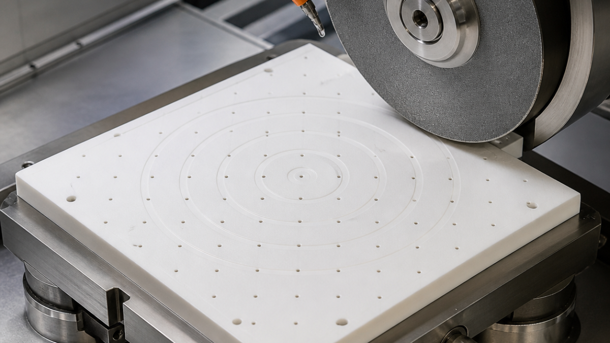
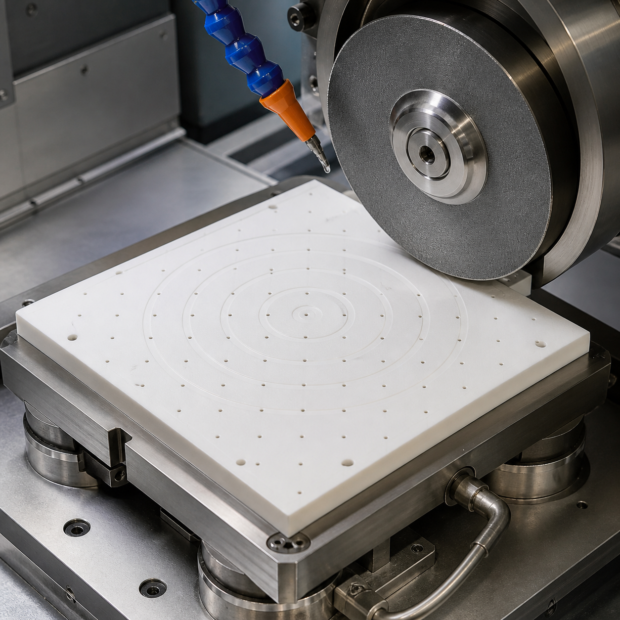
The functional face is datum A with 0.012 mm flatness and Ra 0.4 µm. The rear mounting pads form datum B; a shallow 0.35 mm spiral groove feeds eighty Ø0.6 mm vacuum holes. Overall parallelism is 0.02 mm, while edge breakout may not exceed 0.08 mm. Hole position matters for airflow, but face integrity and leak-free channels govern service. The drawing must also state whether dimensions apply before or after lapping.
Tool selection: diamond does the cutting
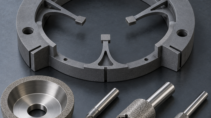
A metal-bond diamond cup wheel rough-grinds the faces, followed by a finer resin-bond diamond wheel for finish. A diamond point dresses groove corners, and electroplated diamond drills open protected micro-holes from both sides. Carbide appears only in soft sacrificial fixture components; conventional carbide end mills are rejected for dense alumina because edge fracture and rapid wear would dominate.
Fixturing and staged stock removal
The first setup supports the plate on three compliant ceramic buttons and lightly clamps outside the finished envelope. Rear pads are ground to create B. After ultrasonic cleaning, B seats on a porous vacuum fixture with independently valved zones. Rough face grinding alternates cross directions and removes no more than 0.08 mm per thermal cycle. The plate is released, cleaned and rested before the next pass so fixture load is not mistaken for flatness.
The spiral channel is interpolated with a small diamond wheel using entry arcs and reduced feed at corners. Micro-holes remain filled with removable wax during face grinding; they are drilled after groove inspection, half-depth from each side to limit exit chipping. Final lapping uses a conditioned plate and sparse abrasive. Coolant filtration below the hole diameter and frequent flushing prevent embedded grit.
Cracks, wheel life and finish control
Grinding power, acoustic emission and microscope checks govern wheel dressing. A glazed wheel raises normal force and can seed subsurface cracks even when the face looks bright. Edge chamfers are ground before the final face pass, not rubbed afterward. The process forbids aggressive ultrasonic deburring at unsupported edges; wax is dissolved and holes are flow-tested instead.
Inspection closes the vacuum circuit
Flatness is measured unrestrained on a three-point stand by interferometry or a calibrated scanning indicator after temperature soak. A CMM checks groove depth and hole locations; white-light microscopy samples Ra and edge breakout. Each zone receives a vacuum-decay test, while filtered air confirms every Ø0.6 mm path is open. Dye penetrant is not assumed suitable; the inspection method must be approved for the ceramic and cleanliness requirement.
FAQ
Can sintered alumina be CNC milled with carbide?
Not economically for this finish-critical case. Diamond grinding and drilling provide lower force and controllable fracture; carbide is reserved for fixture details.
How is 0.012 mm vacuum-chuck flatness verified?
Measure the relaxed plate on three points after thermal stabilization, then compare the free-state result with the mounted condition.
How are ceramic micro-holes kept clear?
Protect them during face grinding, filter coolant below hole size, drill from both sides, clean ultrasonically under a qualified cycle and flow-test every circuit.
Compare the datum logic with flat optical baseplates and the small-hole discussion with small-hole valve plates.