English: GGG60 Orbiting Scroll CNC Case: Involute Flanks, Tip Thickness and Datum Transfer
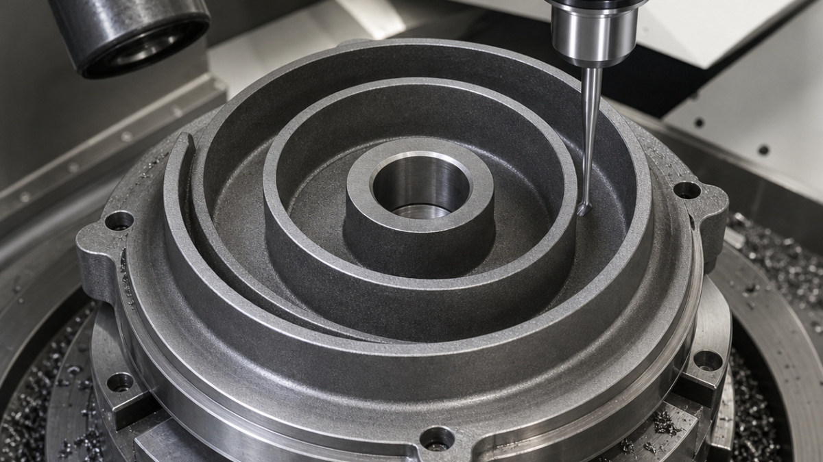
The machining problem in a GGG60 orbiting scroll is not simply following a spiral. Flank profile, wrap-tip thickness, base flatness and bearing-bore position form one error budget. This hypothetical case uses a probe-qualified datum transfer, unequal rough/finish tools and a continuous flank path to keep the compressor clearance predictable.
Build the tolerance budget before choosing a cutter
Datum A is the rear thrust face, B the bearing bore and C a dowel hole. The involute flank has 0.025 mm profile to A-B-C, tip thickness is 2.80 ±0.03 mm, base flatness is 0.018 mm and flank finish Ra 1.2 µm. Root fillet radius is functional because it influences tool access and stress. Casting stock is mapped around twelve angular stations; any local shortage is rejected rather than hidden by shifting the spiral.
Roughing removes skin without spending the finish tool
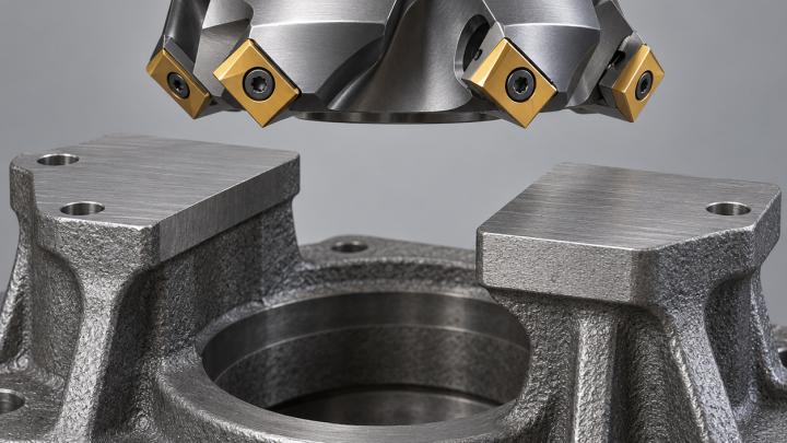
A tough positive carbide face mill establishes A through nodular cast skin. A coated four-flute carbide end mill with reinforced corner roughs the spiral corridor by constant-engagement offsets. The finish tool is a longer, neck-relieved five-flute carbide end mill selected from the narrowest wrap gap, with runout below 0.006 mm. Dry machining with strong extraction is preferred for powdery iron chips; the machine is isolated from incompatible coolant systems.
The datum transfer is probed, not assumed
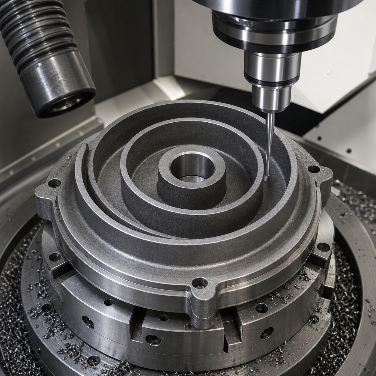
Setup one creates A, roughs B and machines C. Setup two seats A on three clean pads and locates B-C with controlled clearance. Before cutting, a spindle probe measures the bore, three face points and casting stock; the program rotates and translates the nominal involute only within the drawing’s datum rules. Roughing alternates inner and outer flanks so wrap deflection stays balanced, leaving 0.20 mm radial and 0.10 mm on the base.
Semifinishing uses a shorter tool to remove most allowance. The final long-reach tool runs one continuous climb path from outer discharge toward the center, with feed scheduled by engagement and tool deflection. A separate shallow pass finishes the wrap tip; it never uses the flank cutter as an improvised face mill. Root fillets are blended with a small bull-nose carbide tool.
Tip burrs, wear and metrology
Graphite nodules produce abrasive flank wear, while casting skin can chip the corner. Tool life is controlled by profile drift, load and microscope checks. Tip burrs are removed by a programmed 0.12 mm chamfer from both sides, not a hand scraper that changes thickness. A scanning CMM collects inner and outer involute sections at several heights, reports profile to A-B-C, and compares tip thickness. An air gauge verifies B, a flatness scan checks A, and a contact profilometer measures flanks away from the root transition.
FAQ
How is an orbiting-scroll involute inspected?
By scanning both flanks at multiple heights in the functional datum frame, then evaluating profile, tip thickness and the bore relationship together.
Why use separate semifinish and finish end mills?
The short tool removes stock rigidly; the neck-relieved tool is preserved for the deep final flank where deflection directly becomes profile error.
Should ductile-iron scrolls be wet machined?
Either route needs qualification. This case uses dry cutting and extraction to manage abrasive powder and avoid coolant contamination.
Related: deep-rib tool access and ductile-iron datum control.