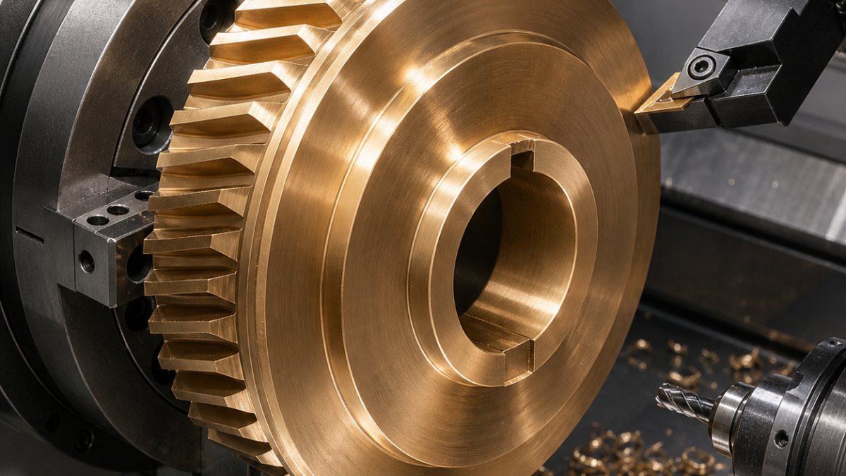
English: C95400 Aluminum Bronze Worm-Wheel Blank CNC Case: Bore Runout, Keyway and Burr Control
What the searcher needs to know: a C95400 aluminum-bronze worm-wheel blank should be finish-turned from its bore on a qualified expanding mandrel, with the tooth rim left as a controlled hobbing allowance and the keyway cut only after the bore-rim relationship is proven. This hypothetical case focuses on preventing built-up edge, cast-skin tool damage and keyway exit burrs.
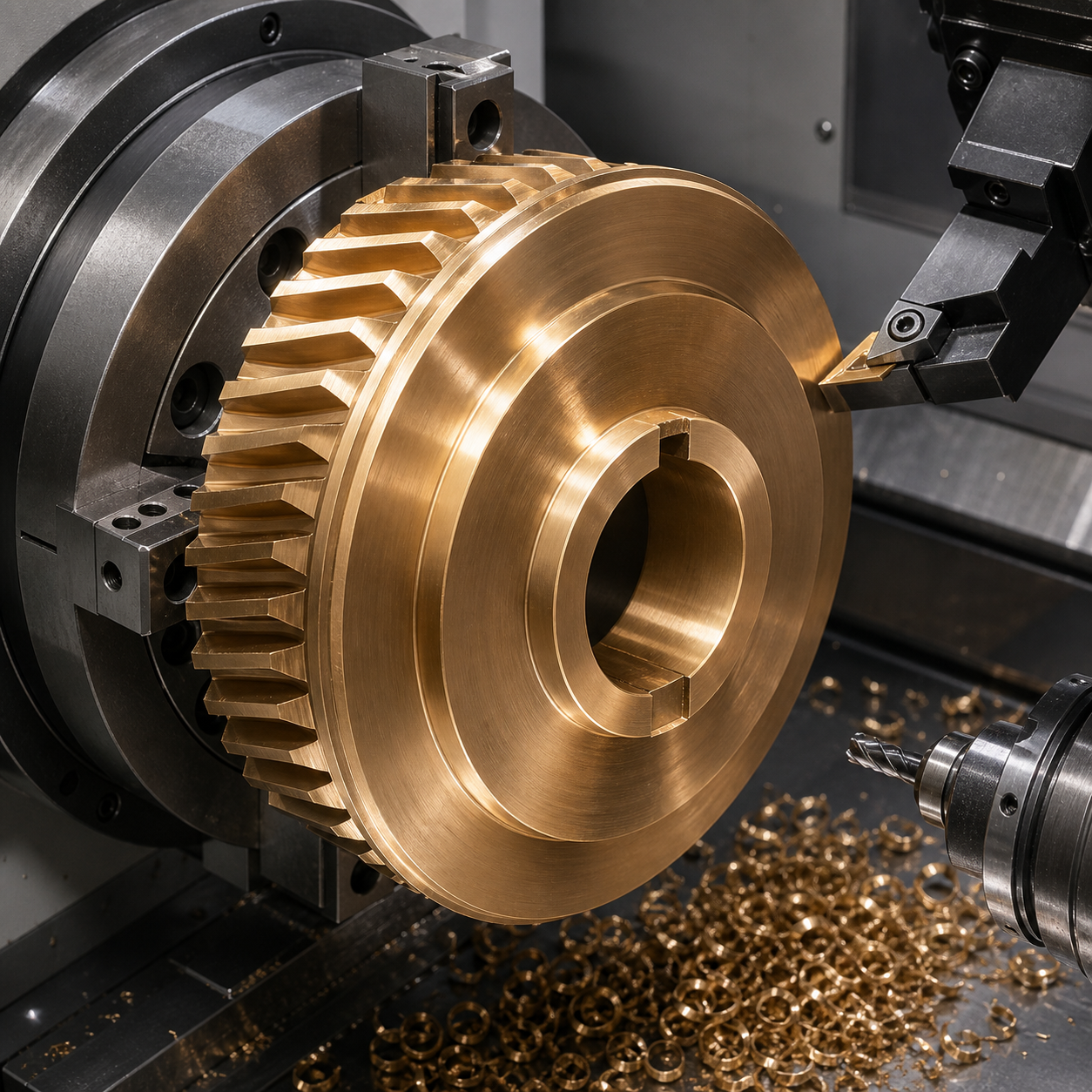
Drawing logic starts with the future gear mesh
The blank is Ø210 mm with a Ø65 H7 hub bore, 42 mm face width and 6 mm keyway. Datum A is the bore axis, B is one hub face and C is the keyway center plane. The pre-hob rim must run within 0.025 mm to A, B has 0.02 mm perpendicularity, and 2.2 mm radial hobbing stock must remain uniformly. The drawing separates final tooth data from blank dimensions so a machinist does not accidentally finish the rim to gear size.
Carbide grades matched to cast skin and clean bronze
The first cut uses a tough uncoated micrograin carbide insert with a positive geometry and a honed edge capable of crossing local cast hardness. Once skin is removed, a sharper polished positive insert controls built-up edge. A solid-carbide boring bar finishes the bore, while a three-flute carbide end mill roughs the keyway and a fresh two-flute tool finishes its width. Copious compatible coolant flushes dense chips from the hub; feed remains high enough to cut rather than rub.
From rough casting to bore-based finishing
At incoming inspection, ultrasonic or dye-compatible checks screen the critical hub-to-rim zone according to the material specification, and casting allowance is mapped at eight clock positions. First turning grips the rough rim in soft jaws, faces B, roughs the bore and leaves 0.5 mm on both functional diameters. The part is reversed on the machined face, the second face is brought parallel, and stress is allowed to equalize before final work.
A dual-taper expanding mandrel locates on the semi-finished bore with axial support near the hub, not beneath the flexible rim. Low clamping pressure is qualified with a roundness check. Bore finishing and rim turning then occur in the same spindle orientation: the boring pass establishes Ø65 H7, a light radial finish produces Ra 0.8 µm, and the outer rim is turned to preserve exactly 2.2 mm hobbing stock. Constant-surface-speed limits avoid overspeed at the rim.
Keyway strategy and chip control
The keyway is milled in a separate indexed setup that references A and B. A sacrificial bronze-backed exit insert supports the breakthrough side. Trochoidal roughing leaves 0.08 mm per wall; a climb-cut finish pass sizes the slot without dragging a built-up edge. Chips are flushed forward and vacuumed before probing. Edge break is a measured 0.15–0.25 mm, not an uncontrolled hand radius.
Tool-life risks and inspection handoff
Cast-skin inclusions can notch the first insert, while clean C95400 can weld to an overly blunt edge. Insert photographs, spindle-load change and bore-finish trend determine replacement. Final inspection uses a CMM or roundness system to build datum A, measure rim runout and B perpendicularity. An air gauge verifies H7 at three axial stations, a calibrated slot gauge checks keyway width, and a radial stock map accompanies the blank to hobbing. Surface roughness and burr height are recorded separately.
FAQ
Why finish a worm-wheel blank on an expanding mandrel?
It makes the functional bore the rotational datum, so rim runout and uniform hobbing stock are controlled directly.
Which carbide geometry suits C95400?
A tough positive insert removes variable cast skin; a sharper polished positive edge then limits built-up edge on clean material.
How much keyway burr is acceptable?
The drawing should define it. In this case a controlled 0.15–0.25 mm edge break replaces subjective hand deburring.
Related reading: bore and keyway datum planning and aluminum-bronze bore finishing.


