English: converting the pulley-hub drawing into operations
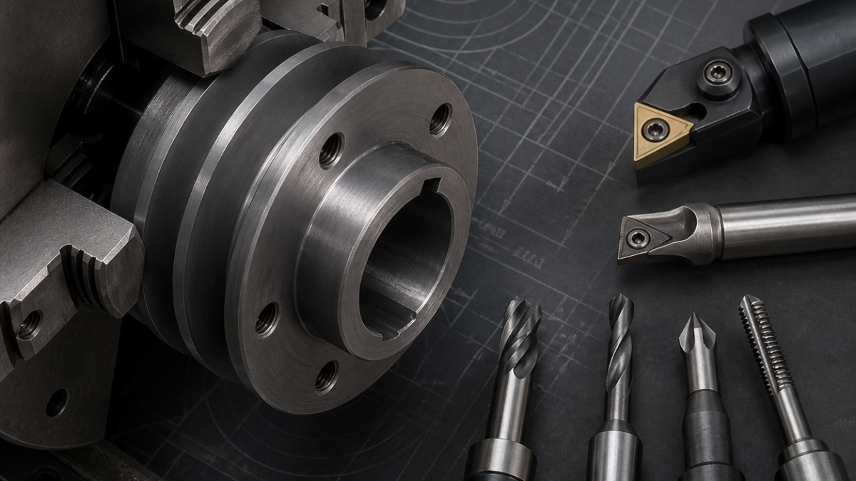
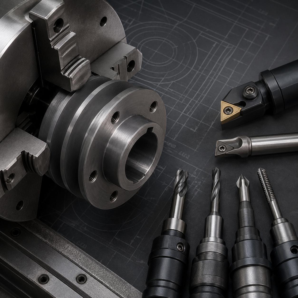
This hypothetical AISI 1045 hub has two functional faces, an external pilot, a precision taper bore, an internal keyway and radial threaded holes that intersect the tapered surface. The drawing should be read as a relationship map: bore taper and face runout govern assembly, while the keyway and threads must be clocked without damaging the finished bore.
Workholding and datum transfer
Face and rough-turn the outside diameter in a three-jaw chuck, then establish the opposite face and pilot in bored soft jaws. Finish the pilot, reference face and taper in one spindle setup. Confirm the taper with a calibrated master or measured axial diameters. Transfer the part to a mill-turn spindle or indexed fixture located on the pilot and reference face; use controlled axial clamping so the bore is not distorted.
Cutting-tool package
- A positive carbide turning insert faces and profiles the normalized 1045 stock.
- A rigid carbide boring bar pre-finishes the hole; a fine boring or contour pass creates the taper with a small, repeatable allowance.
- A reduced-neck carbide end mill plunges through a prepared relief and mills the keyway in staged passes.
- Short carbide drills create the radial holes, followed by a thread mill that can interpolate without pushing a tap into the opposite bore wall.
- A small chamfer mill deburrs hole mouths and the keyway without rolling burrs into the taper.
Toolpath, inspection and tool-life risks
Use consistent feed through the taper finish and avoid a dwell at reversal. Measure tool and spindle runout before the final boring pass. For the keyway, leave a light side allowance and finish each wall separately to control width and centerline. Break the radial-hole intersection with a programmed circular move or a suitable back-deburring tool. Inspect taper contact, axial location, pilot concentricity, keyway width and position, and face runout on the functional datum.
Related reading: gear-shaft datum and runout planning and runout control for carbide tools.