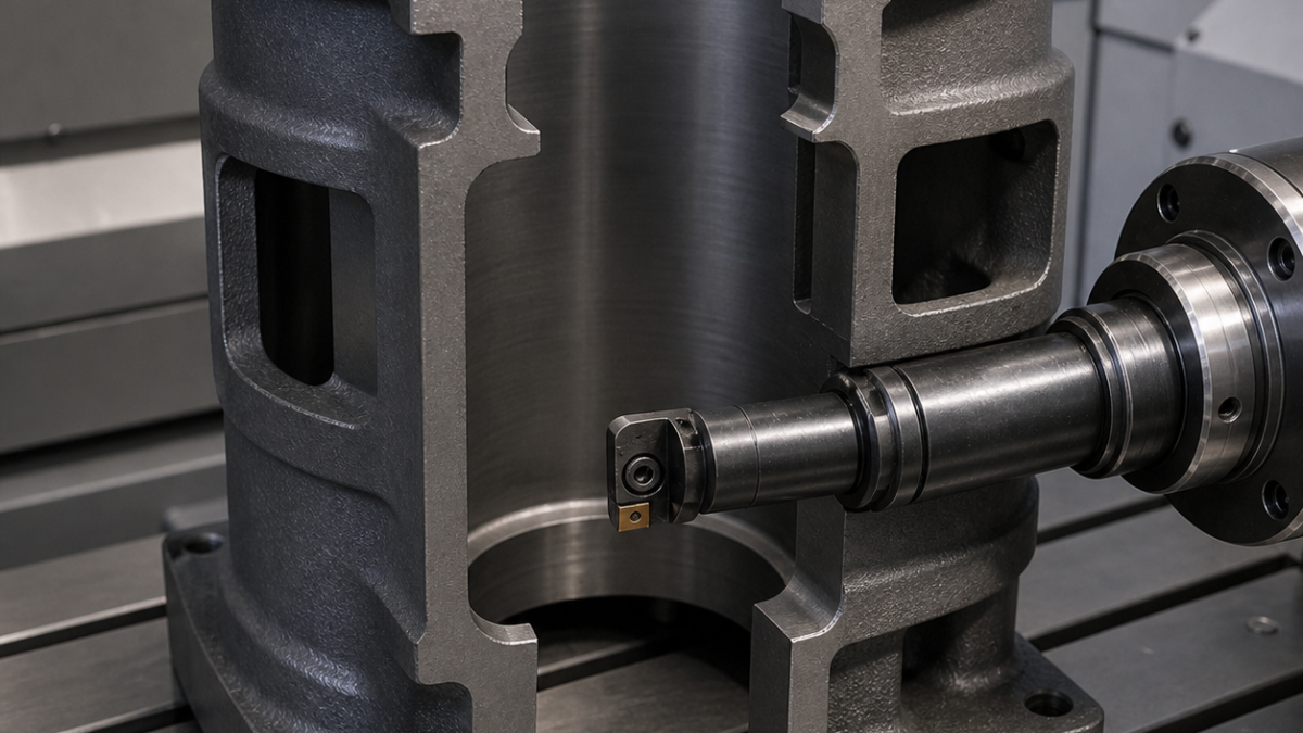
English: EN-GJL-250 Compressor Cylinder Liner CNC Tool Selection for Port Windows and Honing Stock
The correct tooling plan for an EN-GJL-250 compressor cylinder liner starts by protecting the honing stock, not by chasing a finished bore on the machining center. This hypothetical drawing calls for an interrupted port belt, a controlled Ø86 bore with 0.030 mm radial honing allowance, a flange face related to that bore, and burr-free port edges. Short ISO-K carbide boring inserts, a damped semifinish bar, cast-iron slot mills and a reverse-edge tool keep those requirements in one measurable datum chain.
What the hone must inherit
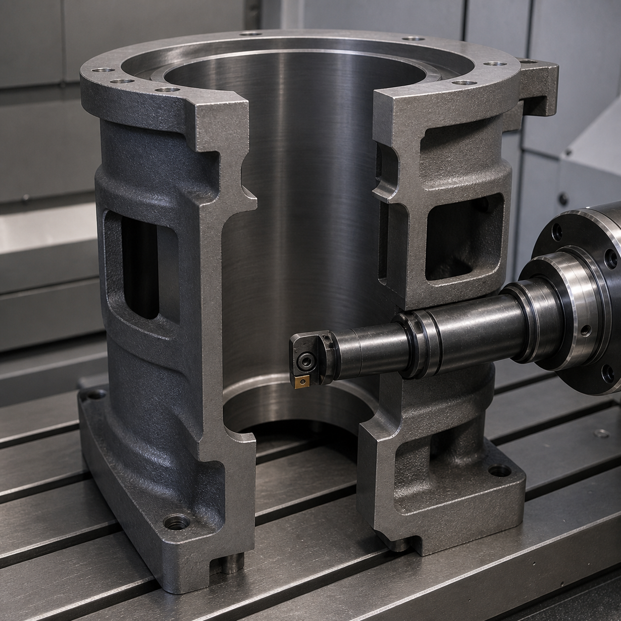
Flange face A locates the liner axially; bore B establishes the working axis; one wide inlet window defines clock datum C. The pre-hone bore is Ø85.940–85.955 mm with cylindricity 0.018 mm, leaving 0.022–0.030 mm radial stock for a final Ø86 H6 plateau-honed surface. Six rectangular windows cross the wall at 60° intervals, with top edges 42.00 ±0.03 mm from A and angular position ±0.08°. The upper counterbore is Ø92 H7, flange runout to B is 0.020 mm, and a 1.20 mm oil groove must not blend into a port corner.
This makes the port belt an interrupted-bore problem. Cutting all windows first weakens the wall before the semifinish bore; finishing the bore first lets window breakouts damage the honing stock. The route therefore roughs both systems, stabilizes the liner, then alternates bore and window finishing around a defined inspection gate.
Tool decisions at each handoff
| Feature and stage | Carbide tool, grade, geometry and holder | Reason and alternative rejected |
|---|---|---|
| Raw flange and OD roughing | CNMG 120408 ISO-K20 CVD TiCN/Al2O3 carbide, medium-positive chipformer, 0.8 mm nose radius, rigid capto holder | The wear-resistant K grade tolerates the cast skin. A sharp aluminium insert chips on sand inclusions. |
| Bore roughing before ports | Ø63 four-edge rough-boring head with ISO-K15 coated carbide cartridges, R0.8, 0° lead, short modular bar | Balanced cartridges remove stock without forcing one long insert bar; high lead would push the slender wall radially. |
| Window opening and corners | Ø12 five-flute fine-grain carbide end mill, AlCrN, 38° variable helix, R0.5, 22 mm reach in a power-shrink holder; Ø6 four-flute R0.3 rest tool | Five flutes suit dry cast-iron chips and distribute the interrupted load. A two-flute aluminium mill has weak support at the window entry. |
| Bore semifinish to honing stock | Positive CCMT 060204 ISO-K10 carbide with CVD wear layer and light T-land, R0.4, internal-air damped bar at 4.5×D reach | The damped bar holds cylindricity after ports exist. PCBN is rejected here because repeated port impacts make edge cost and fracture risk unnecessary at the required pre-hone finish. |
| Ø92 H7 counterbore | Adjustable twin-edge fine-boring head, ISO-K10 carbide, wiper-flat insert, HSK-A100 short adapter | Diameter can be corrected independently of B while the wiper stabilizes Ra 1.6 µm. |
| 1.20 mm internal oil groove | 1.20 mm full-radius PVD-TiAlN carbide grooving insert on a short anti-vibration bar, neutral rake | Neutral radial load prevents groove taper. A form tool that also cuts the port chamfer would be too wide and prone to chatter. |
| Port back edges | Ø10 replaceable-head carbide reverse chamfer tool, four teeth, 45°, AlCrN, through-air holder | It breaks the internal window edge under program control; hand grinding risks scratching the honing allowance. |
| Bolt circle and flange chamfer | Ø6 three-flute ISO-K carbide drill, 140° point; Ø12 six-flute 90° carbide chamfer mill | The drill handles graphite-rich chips; a combined drill-chamfer would tie hole depth wear to the sealing-face edge. |
A route built around the interrupted cut
Operation 10 grips the casting on three qualified OD pads and faces A, turns the flange pilot, and rough-bores B with 0.40 mm radial stock. A light clamp ring replaces hard jaw pressure before the windows are opened. Each port is ramped from its centre, roughed with constant radial engagement, and left 0.08 mm on walls and 0.05 mm at the top edge. Opposite windows are paired so the liner releases symmetrically.
After a thermal pause, the damped bar semifinishes B in two passes: the first reveals interrupted-load variation; the second creates uniform honing stock. The port rest tool then brings C and the remaining windows to position without touching the protected bore. Dry extraction is preferred for loose graphite dust where the machine and risk assessment permit it; otherwise the validated coolant and filtration plan must prevent abrasive recirculation. Flank wear, chipped T-land, a periodic load peak at every window or a lobed bore trace ends the tool’s service.
Inspection handed to honing
An air gauge samples B at three heights and two angular orientations; a roundness instrument distinguishes six-lobe clamp error from taper. A CMM builds A-B-C, measures window height and angle, and checks flange runout. Replica tape or optical inspection confirms the reverse chamfers without touching the bore. Only after cylindricity and minimum honing stock are accepted does plateau honing begin. Final size, cross-hatch, Ra/Rpk/Rvk and cleanliness belong to the validated honing specification, not to unsupported claims in this hypothetical case.
How much machining stock should remain before cylinder-liner honing?
This drawing uses 0.022–0.030 mm radially. The actual allowance must exceed the measured pre-hone form error while staying within the hone’s removal capability.
Which carbide grade suits gray-cast-iron port windows?
A wear-resistant ISO-K fine-grain carbide with an AlCrN or proven cast-iron coating and a supported corner handles the interrupted entry better than a sharp, low-support aluminium geometry.
Why deburr the port from inside with a reverse tool?
The programmed back chamfer removes the breakout lip without dragging an abrasive across the precision bore or consuming uneven honing stock.
Related cases: cast-iron bore and face tooling and controlled carbide chamfering.


