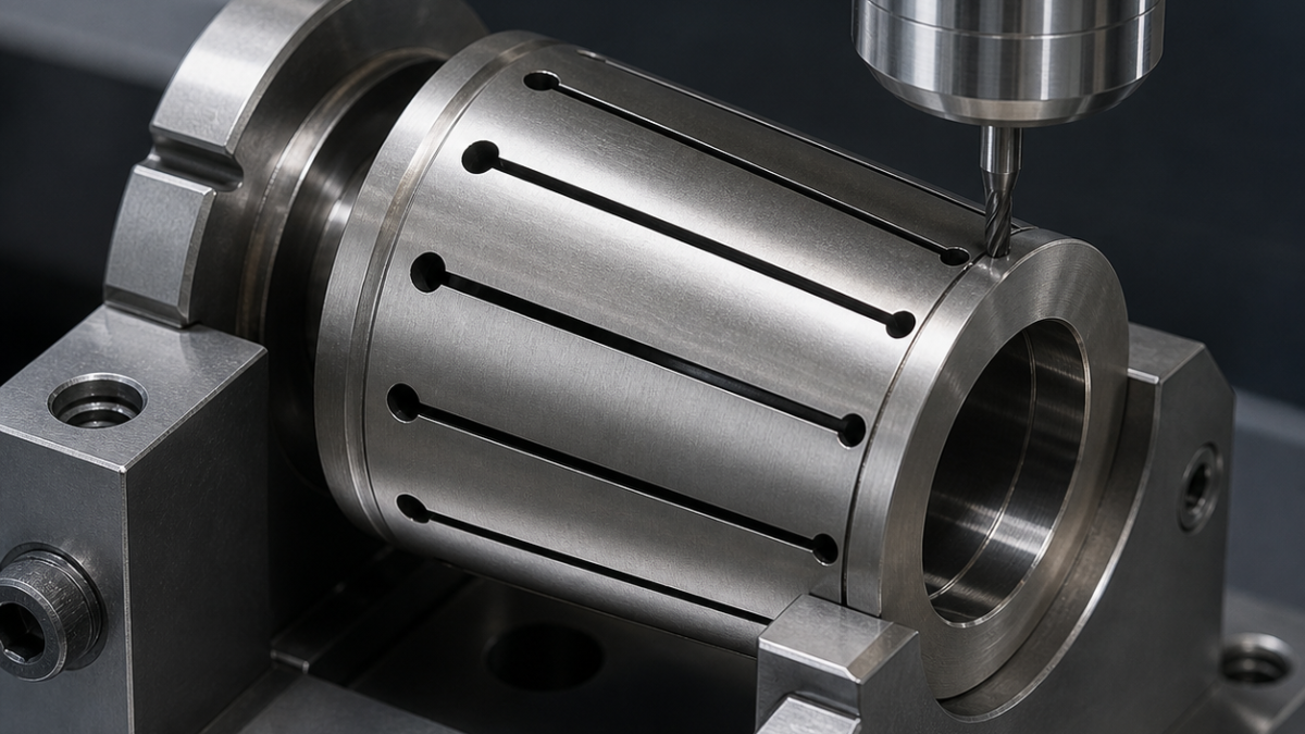
English: Nitinol Actuator Collet CNC Tool Selection for 0.35 mm Flexure Slots and Thin Fingers
A Nitinol actuator collet with 0.35 mm flexure slots should be tooled from the failure sequence backward: first prevent finger movement, then prevent work-hardened slot walls, and only then chase the free-state bore. In this hypothetical drawing, twelve relief holes and slots create spring fingers around an Ø8 H7 bore. A supported sacrificial ring, low-hone PVD-coated carbide microtools, a neutral grooving insert and post-release probing provide a practical route without pretending that clamped dimensions equal functional dimensions.
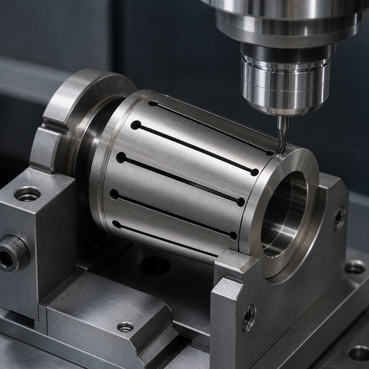
Three states hidden in one drawing
Before slotting, datum face A, pilot diameter B and index notch C locate the sleeve. The solid state carries an Ø7.92 mm semifinished bore and a 20.00 mm outside diameter. The supported state adds twelve Ø0.80 relief holes connected to 12.0 mm-long slots, each 0.350 +0.025/0 mm, leaving fingers 1.20 ±0.025 mm wide. In the released state, bore B must be Ø8 H7, finger-tip radial spread must remain within 0.040 mm, the external retention groove is 0.80 ±0.02 mm wide, and slot walls require Ra 1.6 µm without a continuous burr.
Nitinol can work-harden and recover elastically around the cutter. The program does not use dwell or repeated rubbing passes to “clean” a slot. Each tool has a defined minimum chip thickness, entry path, maximum engagement count and inspection signature.
Failure-led feature-to-tool map
| Failure to prevent | Drawing feature and selected carbide tool | Why the competing choice is rejected |
|---|---|---|
| Bore closes after finger release | Solid-state rough bore: positive CCGT 060202 PVD-AlTiN fine-grain carbide, R0.2, 7° clearance on a short steel bar; released finish: Ø7.7 pilot then adjustable micro-boring head with a polished AlTiN carbide insert, R0.1 | A fixed Ø8 reamer would follow the distorted supported bore and cannot correct the released axis. |
| Outside diameter pushes the sleeve off axis | VCGT 110302 PVD-TiAlN carbide, sharp 6–8 µm edge preparation, R0.2, rigid Swiss-style holder | A heavily honed negative insert raises heat and radial force on the thin tube. |
| Relief holes smear or crack at breakout | Ø0.80 two-flute through-coolant carbide drill, 140° split point, AlTiN, 2.5 mm flute length, precision collet | A centre drill plus long peck cycle causes extra rubbing; laser holes are not substituted because recast and thermal effects are outside this drawing route. |
| 0.35 mm slots taper or harden | Ø0.30 three-flute necked micro end mill, AlTiN nanolayer, 25° helix, 12.6 mm reach, 4–6 µm hone, shrink-fit holder with verified 0.002 mm runout | A full-width Ø0.35 cutter has no compensation room; a slitting saw cannot follow the cylindrical index without a new fixturing error. |
| Slot floor leaves a stress raiser | Ø0.60 two-flute AlTiN carbide ball end mill, 8 mm neck, tangent blend into the predrilled Ø0.80 relief | A sharp square termination concentrates strain; the ball path blends without recutting the long slot walls. |
| Retention groove springs open | 0.80 mm neutral PVD-TiAlN carbide grooving insert, ground positive flanks, 0.05 mm corner radii, compact gang holder | A wide negative groover deflects the sleeve and masks width recovery while clamped. |
| Finger edges carry a continuous burr | Ø1.5 four-flute 45° AlTiN carbide lollipop-style back-chamfer tool, 0.03 mm programmed break, slim hydraulic holder | A rotary brush may bend fingers and smear the spring alloy; manual stones cannot maintain twelve equal edges. |
| Threaded mounting holes gall | Ø1.60 AlTiN carbide drill and Ø1.25 three-flute single-form carbide thread mill for M2, internal coolant holder | Thread milling avoids tap reversal and permits pitch-diameter compensation in a work-hardened hole. |
Sacrificial ring, one-direction slots and release
The tubular blank is supported on a precision expanding mandrel at the unslotted land; a split polymer-metal nest contacts the OD without forcing the future fingers round. A 2.0 mm sacrificial end ring remains beyond the finished tips. A, B, C, the OD, groove and relief holes are completed while the cylinder is solid. Hole position is probed before a single slot is opened.
Slots are machined in a 1-7-4-10 opposite sequence. The Ø0.30 tool enters through the Ø0.80 relief, makes a trochoidal centreline rough path leaving 0.018 mm per wall, and takes one climb-finish pass in the same axial direction for every finger. It never dwells at the closed end. High-pressure, well-directed coolant clears short chips, while maximum spindle load and acoustic signature are recorded for the first slot. A polished band, rising load, width taper or corner microchipping retires the tool before it is allowed into the next opposite pair.
After all edges are broken, the sacrificial ring is removed in two alternating arc segments so the fingers do not release at once. The part rests at the inspection temperature. Only then is the bore lightly finish-bored on a soft expanding support, using measured radial recovery rather than the supported offset.
Measurement closes the state loop
A vision system measures each slot at three axial stations and compares opposite finger widths. A low-force scanning probe builds the released bore and tip envelope; a roundness trace separates harmonic spring recovery from tool taper. Groove width is checked both on the support and free state, and white-light metrology confirms slot-wall finish and the blended relief. The machining record includes tool runout, slot order and pre/post-release dimensions so a change in material transformation behaviour is visible rather than hidden in a final pass.
What end mill should cut a 0.35 mm slot in Nitinol?
A Ø0.30 necked, low-hone AlTiN carbide micro end mill provides wall compensation and reaches the relief hole; the exact speed and chip load must be qualified to avoid rubbing.
Why keep a sacrificial ring on the finger tips?
It keeps all fingers in one cylindrical stiffness state during slotting and chamfering, then allows controlled release before final bore correction.
Can wire EDM replace micro milling for the flexure slots?
It may be a separate qualified route, but recast, heat-affected condition, corner geometry and cleaning would require their own drawing acceptance; it is not treated as an automatic substitute here.
Related guides: heat and notch-wear control in nickel alloys and selecting carbide-tool coatings.


