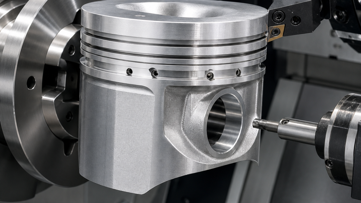
English: A390 Piston CNC Tool Selection for Ring Grooves, Pin Bore and Oval Skirt
An A390 hypereutectic-aluminium piston should not be finished with ordinary aluminium tooling. Primary silicon rapidly rounds carbide edges, while a wide form blade can bend the ring land and an ordinary circular turning cycle cannot create the specified oval skirt. This hypothetical tooling plan uses carbide for controlled roughing and holemaking, dedicated PCD edges for the ring grooves and pin bore, and a non-round turning unit for the barrel-and-oval skirt profile.
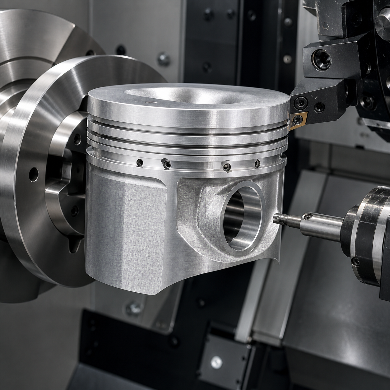
Convert the piston drawing into machining states
Crown face A and the wrist-pin axis B establish the functional frame. The pin bore is Ø22 H6 with two bosses coaxial within 0.010 mm. The first compression groove is 1.20 +0.015/0 mm wide, the second is 1.50 +0.020/0 mm, and the oil groove is 2.80 +0.030/0 mm with six Ø2.0 drain holes. The skirt has a 0.18 mm major-to-minor oval difference and a barrel profile limited to ±0.020 mm at the drawing gauge heights. Groove flanks require Ra 0.8 µm; torn silicon particles and rolled drain-hole burrs are reject conditions.
The drawing dimensions are assigned to three states: supported roughing, thermal stabilization, and free-state final measurement. Mixing offsets from those states would make a warm round skirt look correct while the stabilized oval profile is wrong.
Tool map for abrasive high-silicon aluminium
| Feature | Selected tool and holder | Decision and rejected alternative |
|---|---|---|
| Cast skin and crown roughing | Ø12 three-flute DLC-coated fine-grain carbide end mill, 45° polished flutes, R0.5, 0.03 mm edge prep, hydraulic holder | DLC limits adhesion and carbide survives interrupted skin; a PCD edge is reserved until porosity and hard skin are removed. |
| Combustion bowl semifinish | Ø8 three-flute diamond-coated carbide ball end mill, R4, 24 mm reach, shrink-fit holder | Leaves 0.10 mm normal stock with controlled scallop; a long two-flute aluminium cutter wears quickly on primary silicon. |
| Crown and land finish | Positive PCD turning insert, 20° polished rake, R0.4, 0.02 mm edge hone, rigid short tool block | Maintains size and low roughness; uncoated carbide loses flank clearance too quickly. |
| Compression-ring grooves | Separate 1.05 and 1.35 mm PCD grooving blades for roughing, then width-specific PCD side-finishing blades, zero-rake land, minimum blade overhang | Each flank receives compensation; a full-width form blade loads the thin ring land and hides asymmetric wear. |
| Oil groove and drain holes | Ø2.4 PCD grooving blade followed by Ø2.0 two-flute DLC carbide drills, 130° split points, 8 mm flute length, precision collets | Drills enter from the groove after probing; a long standard drill can wander across the curved boss. |
| Ø22 H6 pin bore | Ø18 three-flute diamond-coated carbide helical rougher, then positive PCD fine-boring insert R0.2 on a damped short bar | Fine boring corrects both bosses to axis B; a reamer follows any misalignment and cannot trim coaxiality. |
| Barrel-and-oval skirt | R0.8 PCD profiling insert in a qualified fast non-round turning unit, balanced holder, calibrated radial actuator | The tool follows the drawing polar profile; ordinary OD turning produces a circle and milling leaves lobed facets. |
| Edge breaks | Ø6 three-flute DLC carbide 90° chamfer mill, 0.10 mm programmed break | Controls the drain exits without abrasive hand deburring near the skirt. |
Fixture handoff, roughing and finish release
The casting is first gripped below the future skirt gauge band. The crown, bowl and internal relief are roughed with adaptive toolpaths at low radial engagement, keeping the cutter in fresh material and evacuating silicon-rich chips with filtered flood coolant. The ring lands are semi-turned but the grooves remain closed until crown face A is stable.
For the second operation, a conforming soft mandrel locates the crown register and supports the pin bosses. The pin bore is roughed from both sides and fine-bored through in one aligned setup. Groove roughers enter axially, leave 0.05 mm per flank and withdraw without dwelling; the finishing blades then cut one flank at a time. After a temperature pause, the non-round unit machines the skirt from lower gauge band toward the ring belt. A dusty grey flank, increasing groove width or exposed torn silicon retires the edge.
Inspection plan and FAQ
An air gauge and master confirm the H6 pin bore, while a coaxial probe checks both bosses. A polar scanning fixture measures skirt ovality and barrel profile at every drawing height. Groove width, flank angle and root radius are measured by contour trace; the crown and bowl are checked on a CMM. Borescope inspection verifies that oil-hole exits are open and burr-free before cleaning.
Why does A390 piston machining use PCD tools?
The alloy’s primary silicon is highly abrasive. PCD holds flank clearance and groove width longer than conventional carbide on the finish cuts.
Can one full-width blade finish a piston ring groove?
It can cut the nominal width, but this plan rejects it because simultaneous flank load deflects the land and prevents independent wear compensation.
How is an oval piston skirt machined?
A calibrated non-round turning actuator drives a PCD profiling insert to the drawing’s polar radius while the spindle rotates.
Compare the wear logic with PCD selection for abrasive aluminium finishing and the datum handoff with cast-aluminium bore and pilot tooling.


