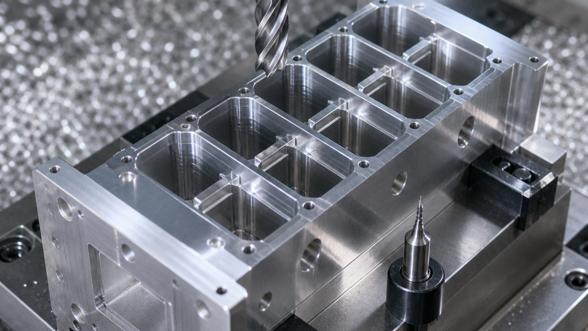
English: 7075-T651 Waveguide Filter CNC Tooling Case: Thin Iris Walls and Cavity Corners
For a 7075-T651 waveguide filter body, the drawing-to-tool decision is governed by the 1.0 mm iris walls and R0.6 cavity corners—not by the largest open pocket. This hypothetical case answers how to select carbide tools that rough quickly without bending the RF partitions, then finish the cavity geometry and sealing deck without burrs or tool-mark steps.

Drawing features and functional priorities
Datum A is the cover-seal deck, B and C are orthogonal dowel bores. Six stepped resonator cavities are 28 mm deep; iris thickness is 1.00 ±0.03 mm, corner radius R0.60 +0.05/0 mm, cavity profile 0.025 mm to A-B-C and deck flatness 0.020 mm at Ra 0.8 µm. RF performance depends on cavity width and iris location, while the outer block can tolerate a broader profile. Stock is stress-relieved before the thin separators are released.
Feature-to-tool selection
| Drawing feature | Selected tool | Reason and rejected alternative |
|---|---|---|
| Open cavity volume | Ø10 mm, 3-flute polished uncoated carbide, 35° helix, shrink holder | High chip space and sharp edge; a 4-flute coated steel tool packs aluminum chips. |
| Near-iris semifinish | Ø4 mm, 3-flute polished carbide, reduced neck, 18 mm reach | Short cutting length supports the wall; a long general-purpose cutter deflects. |
| R0.6 corners | Ø1.2 mm, 2-flute micro carbide, 6 mm flute, hydraulic micro chuck | Matches the radius with runout below 0.004 mm; EDM would add handoff and recast risk. |
| Seal deck | Ø40 mm PCD face mill with wiper insert | Stable Ra and low burr; a small end mill creates stitch marks. |
| Dowel bores | Carbide drill plus fine boring head | Boring corrects position; a reamer follows a displaced pilot. |
Toolpaths, fixture and material risks
Operation one machines A, rough dowel pilots and leaves 0.3 mm in cavities. Operation two locates A-B-C on a vacuum fixture with perimeter stops. Adaptive roughing opens alternate cavities so both sides of each iris retain similar stiffness. Near the wall, radial engagement falls below 8% of diameter. The Ø4 tool semifinishes both faces of an iris in alternating depth bands; the Ø1.2 tool only cleans corner residuals and never removes bulk stock.
Climb-only finish paths run from the wall root toward the supported perimeter. Air blast and minimum compatible lubricant prevent recutting. A rising spindle-load trend, white smeared edge or width drift indicates aluminum built-up edge. Tool length is measured warm, but cavity inspection occurs after thermal stabilization. Burrs receive a programmed 0.08 mm chamfer with a 90° polished carbide spot tool; hand scraping the iris is forbidden.
Inspection and search-focused FAQ
A CMM builds A-B-C, scans cavity widths at three depths, locates each iris center plane and measures corner radius. Optical measurement checks 1.0 mm walls without probe pressure. Deck flatness and Ra are verified after the final face pass; a cover-fit and leak-path check confirms sealing.
What end mill should finish a 1 mm waveguide iris?
Use the largest short, polished carbide tool that fits the adjacent geometry; here Ø4 mm finishes the faces, while Ø1.2 mm is reserved for R0.6 residuals.
Why not rough every cavity before finishing?
Alternating roughing retains balanced support on both sides of each thin partition.
How are RF cavity corners inspected?
Combine CMM profile scans with optical corner-radius measurement in the functional datum frame.
Related guidance: thin-wall pocket support and long-reach tool control.
中文: 7075-T651波导滤波器配刀:薄隔片与腔体小圆角
7075-T651波导滤波器的配刀基准不是最大腔体,而是1.0 mm薄隔片和R0.6角部。本假设案例说明如何用硬质合金刀具高效开粗,同时避免射频隔片弯曲,并完成无明显毛刺的腔体与密封面。
图纸重点
A为盖板密封面,B、C为正交定位孔。六个腔体深28 mm,隔片1.00 ±0.03 mm,角部R0.60 +0.05/0 mm,腔体对A-B-C轮廓度0.025 mm,A面平面度0.020 mm、Ra 0.8 µm。
特征—刀具配刀表
| 特征 | 刀具 | 选择理由 |
|---|---|---|
| 大面积开粗 | Ø10三刃抛光无涂层硬质合金,35°螺旋,热缩刀柄 | 容屑大;普通四刃钢件刀容易堵屑。 |
| 隔片附近半精 | Ø4三刃抛光缩颈刀,有效刃长18 mm | 短刃提高刚性,拒绝长刃通用刀。 |
| R0.6角 | Ø1.2两刃微径硬质合金,液压微夹头 | 跳动小于0.004 mm;不为小残料引入EDM交接。 |
| 密封面 | Ø40 PCD修光面铣刀 | 减少接刀纹和毛刺。 |
| 定位孔 | 硬质合金钻+精镗刀 | 精镗能修正孔位,铰刀只会随预孔。 |
刀路与风险
先建立A并预加工B、C,第二序用真空夹具定位。腔体交替开粗,使隔片两侧刚性平衡;靠墙径向吃刀小于刀径8%。Ø4刀分深度交替半精隔片两面,Ø1.2刀只清角部残料。顺铣精刀从隔片根部向支撑外缘走,气流与微量润滑防止再切削。负载升高、发白拖抹或槽宽漂移表示积屑瘤。90°抛光点钻程序化倒0.08 mm小角,禁止手刮薄片。
检验与常见问题
三坐标在三个深度扫描腔宽和隔片中心面,光学系统无接触测1 mm壁厚与R0.6。最终检查A面平面度、Ra和盖板贴合。
1 mm隔片用多大刀精加工?
用几何允许的最大短刀加工侧壁;本案例Ø4负责侧壁,Ø1.2只清圆角。
为什么腔体交替开粗?
避免先释放隔片一侧导致偏移。
小圆角怎样验收?
在功能基准系中结合三坐标轮廓扫描与光学半径测量。
Français: Filtre guide d’ondes 7075 : outils pour iris fins et petits rayons
Le choix d’outil est imposé par l’iris de 1 mm et le rayon R0,6, non par la grande poche. Le cas relie chaque fonction du plan à un carbure précis.
Tableau fonction-outil
| Fonction | Outil | Décision |
|---|---|---|
| Ébauche | Carbure poli Ø10, 3 dents, hélice 35°, fretté | Grand dégagement; quatre dents colmatent. |
| Flanc d’iris | Carbure Ø4, 3 dents, col dégagé, portée 18 mm | Rigidité supérieure à une longue fraise universelle. |
| R0,6 | Microfraise Ø1,2, 2 dents, mandrin hydraulique | Faux-rond sous 0,004 mm. |
| Plan de joint | Fraise PCD Ø40 à racleur | Ra stable sans raccords. |
| Pions | Foret carbure puis alésage fin | Corrige la position, contrairement à l’alésoir. |
Gamme
A-B-C sont créés avant un montage à vide. Les cavités sont alternées; l’engagement près de l’iris reste sous 8%. Ø4 semi-finit les deux côtés par niveaux alternés, Ø1,2 ne retire que le résiduel. L’air et la lubrification limitent l’arête rapportée. Un outil poli à 90° crée un chanfrein de 0,08 mm.
Contrôle et FAQ
La MMT scanne les cavités à trois profondeurs; l’optique mesure iris et rayons. Planéité, Ra et ajustement du couvercle terminent le contrôle.
Quelle fraise pour l’iris?
La plus grande fraise courte compatible: Ø4 pour les flancs, Ø1,2 seulement aux angles.
Pourquoi alterner les poches?
Pour équilibrer le soutien de l’iris.
Comment mesurer R0,6?
Par profil MMT et optique dans A-B-C.
Voir les parois minces et les longues portées.
Русский: Фильтр 7075: инструмент для тонких перегородок
Инструмент выбирают по перегородке 1 мм и радиусу R0,6, а не по большой полости.
Соответствие элементов и инструмента
| Элемент | Инструмент | Причина |
|---|---|---|
| Черновая полость | Полированный карбид Ø10, 3 зуба, 35°, термопатрон | Место для стружки; 4 зуба забиваются. |
| Перегородка | Ø4, 3 зуба, разгруженная шейка, 18 мм | Жёстче длинной универсальной фрезы. |
| R0,6 | Ø1,2, 2 зуба, гидропатрон | Биение менее 0,004 мм. |
| Уплотнение | PCD Ø40 | Меньше следов стыков. |
| Базовые отверстия | Карбидное сверло и расточная головка | Расточка исправляет положение. |
Процесс
После A-B-C деталь ставят на вакуум. Полости чередуют, у перегородки зацепление ниже 8%. Ø4 обрабатывает стороны, Ø1,2 — только углы. Воздух удаляет стружку; фаска 0,08 мм выполняется программно.
Контроль и вопросы
КИМ сканирует три глубины, оптика измеряет стенку и R0,6.
Какая фреза для стенки?
Максимальная короткая: Ø4; Ø1,2 лишь для углов.
Зачем чередовать полости?
Для равной опоры стенки.
Как проверить угол?
КИМ и оптика в A-B-C.
См. тонкие стенки и вылет инструмента.


