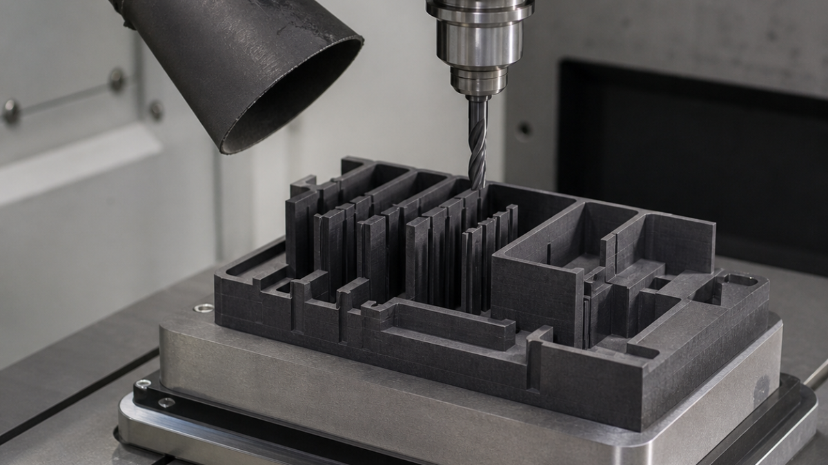
English: Graphite EDM Electrode CNC Case: Thin Ribs, Corner Detail and Dust Control
Direct answer: a fine-grain graphite EDM electrode with tall ribs is safest to machine by defining electrode polarity and burn allowance before CAM, supporting the blank across a broad datum, roughing open regions before narrow slots, and using sharp diamond-coated carbide with continuous dust extraction. This is a newly conceived hypothetical process, not a customer claim.
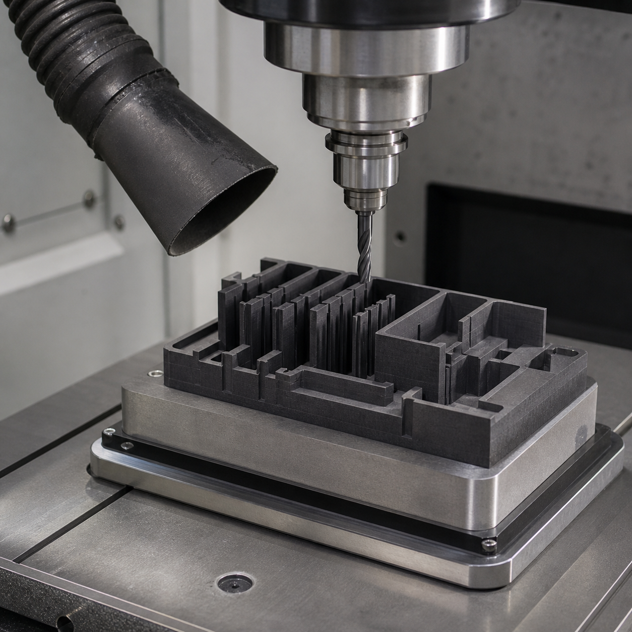
The drawing is an inverse geometry contract
The 82 × 64 mm electrode has 28 mm ribs only 1.2 mm wide, 0.4 mm internal radii, a 0.18 mm rough-burn undersize and 0.06 mm finish-burn undersize. Datum A is the holder face; B and C are orthogonal reference flats. The print must distinguish electrode dimensions from final cavity dimensions and state whether orbit is included. Rib thickness and root radius outrank cosmetic outside faces because one chipped rib changes the spark gap.
Tooling follows fragility, not metal-removal rate
A 6 mm diamond-coated carbide end mill clears open stock, a 2 mm necked carbide tool semi-finishes channels, and a 0.8 mm two-flute diamond-coated cutter resolves the roots. Short flute length and balanced holders reduce runout. Dry machining with a graphite-rated vacuum captures powder at source; coolant is excluded from this route because wet sludge would contaminate the holder and metrology. A fresh tool is reserved for the finish electrode.
Stock removal is sequenced from open to confined
The blank is bonded to a reusable pallet with a thin, uniform adhesive film and positive side stops; vacuum alone is not trusted across a porous surface. A planar skim establishes A, then adaptive roughing leaves 0.25 mm on walls and 0.15 mm on floors. Wide cavities are completed first so extraction remains effective. Slots alternate by location rather than being cut consecutively beside one rib. Semi-finishing reduces the allowance to 0.04 mm, and one climb-only pencil pass finishes each root. Leads enter in open space; plunges beside ribs are prohibited.
Chipping, dust and tool-life decisions
Graphite makes discontinuous powder, so chip recutting appears as polished streaks and rounded corners rather than a conventional built-up edge. Vacuum flow is checked at the nozzle, spindle load is trended, and a 10× camera compares the smallest root after each group. Tool replacement is triggered by radius growth or edge breakout, not an invented part count. Manual abrasive blending is barred because it changes the discharge gap.
Inspection closes the EDM allowance loop
An optical CMM establishes A-B-C and measures rib width, root radius, height and the programmed undersize. A flatness check verifies the holder face before and after release. Critical corners are compared with a calibrated profile image, while continuity and dust-free mounting surfaces are visually confirmed. The inspection report identifies rough and finish electrodes separately so the EDM operator cannot swap offsets.
FAQ
What carbide coating works for graphite electrodes?
Diamond-coated micrograin carbide is preferred here because abrasive graphite rapidly rounds ordinary edges.
How can thin graphite ribs be kept from chipping?
Use low-runout short tools, balanced stock removal, open-space entries, small finishing allowance and no hand blending.
Should graphite be machined wet or dry?
Both require a qualified system; this case uses dry cutting with graphite-rated source extraction and isolated dust handling.
Related reading: EDM allowance planning and tool-overhang control.


