English: AZ91D Magnesium Gimbal Yoke CNC Case: Thin Arms, Pivot Bore and Chip-Fire Control
Search intent answered: machining an AZ91D magnesium gimbal yoke succeeds when the two slender arms remain supported until the pivot bores are finished, the bore axis is established from functional datums rather than the raw casting, and dry chips are removed continuously under a magnesium-specific fire plan. This hypothetical case explains a defensible route from drawing review to inspection without claiming production history.
Read the drawing as a stiffness problem
The drawing defines datum A on the mounting pad, datum B on the central pilot and datum C on one clocking hole. The 96 mm arm span carries two Ø12 H7 pivot bores with a 0.03 mm common-axis requirement to A; arm thickness is 4.5 mm, pad flatness is 0.05 mm and the finished pocket floor is 1.8 mm. A blanket profile tolerance would be misleading: the bore relationship governs motion, while outside arm contours mainly preserve clearance. Stock is therefore left on the arms until the pivot line is complete.
Carbide tools and a fire-aware cutting environment
Sharp polished uncoated carbide is selected: a three-flute high-helix end mill for open pockets, a short two-flute cutter for floor corners, a carbide drill followed by a fine boring head for each pivot bore, and a 45-degree carbide chamfer tool. Edge hone must be minimal because rubbing raises heat. Dry air blast and a dedicated vacuum rated for combustible metal dust evacuate chips; water-based coolant is not casually introduced. Class D extinguishing media, clean sumps and segregated chips are process requirements, not afterthoughts.
Two fixtures, one controlled release
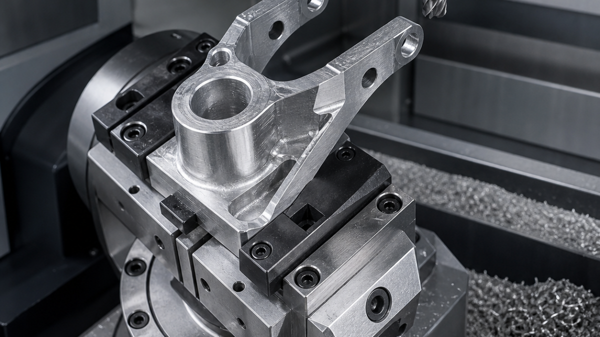
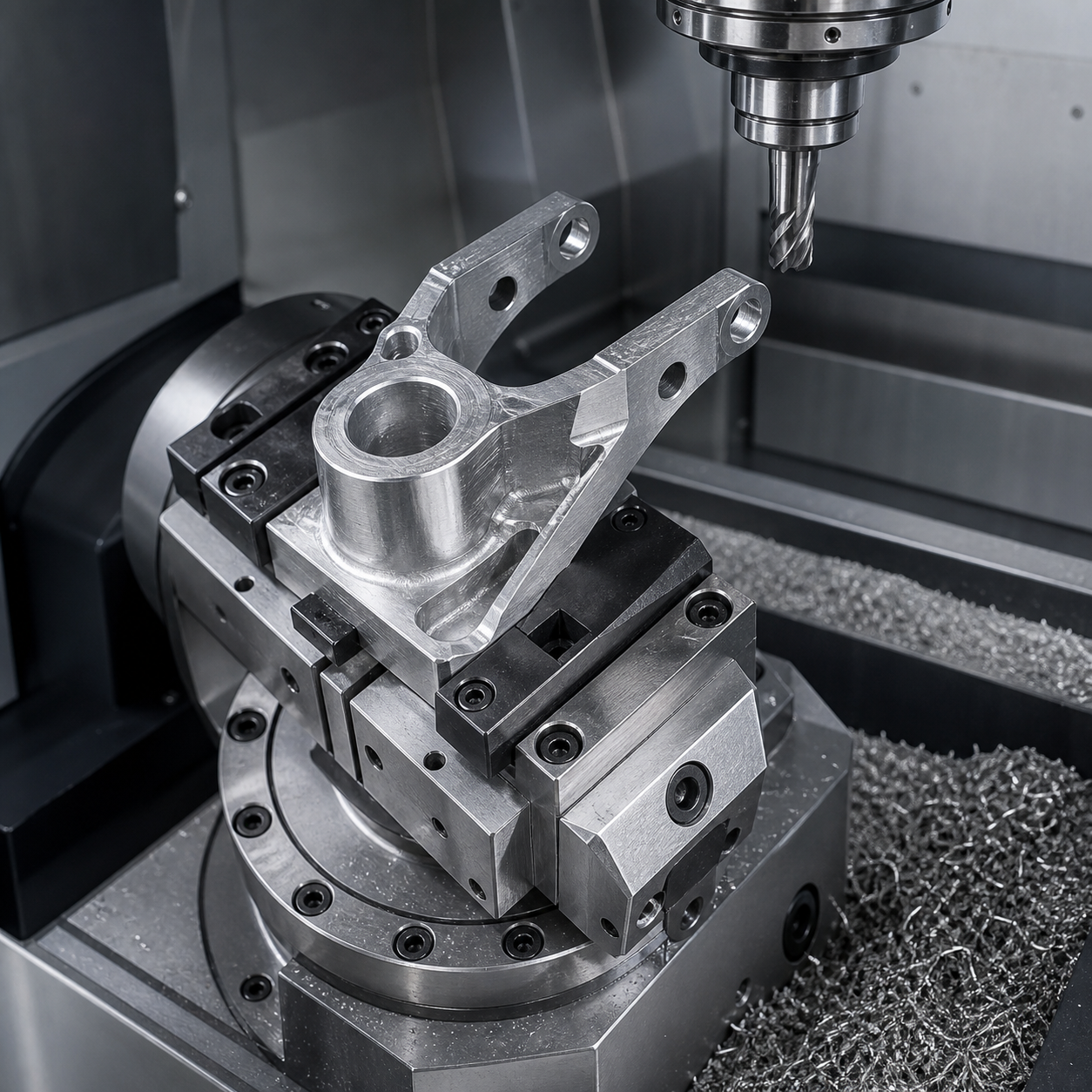
Operation 10 clamps the casting on three sacrificial pads and machines A, the pilot and clocking hole. Operation 20 locates on those finished features in a nest with removable supports beneath both arms. Adaptive roughing uses constant engagement, climb cutting and a shallow axial step to avoid grabbing. Pockets are opened symmetrically left-right so residual stress is not released on one arm alone. A 0.4 mm radial and 0.25 mm floor allowance remain.
The pivot bores are drilled undersize, circular-interpolated and finish bored in one indexed setup. Support buttons stay engaged during boring. Only after the axis passes an in-process probe check are the outside profiles and support tabs removed. A spring pass at full finishing feed is avoided; instead, a measured wear offset controls size. Final contours use a short polished carbide end mill with low radial engagement and a single directional finish pass for Ra 1.6 µm.
Chip control, burrs and tool-life signals
Small dry chips are desirable, but recutting is not. Air nozzles aim away from cavities and extraction is verified before the spindle starts. Long dwell marks, a rising spindle-load trend or a grey smeared edge indicate a dull cutter. Tools are retired by edge quality and load trend rather than an invented fixed part count. Bores receive a light front-and-back chamfer; abrasive hand blending near the thin arms is prohibited because it can alter the datum relationship.
Inspection plan tied to function
A surface plate confirms pad flatness before release. A CMM builds A-B-C, measures both bore cylinders and reports their common axis, span and perpendicularity. Air gauging or certified plug gauges verify Ø12 H7 after temperature stabilization. Arm thickness is mapped at root and tip, and a fixture-mounted indicator compares free-state deflection before and after support removal. Visual inspection also confirms no embedded chip, smeared edge or ignition damage.
FAQ
Should AZ91D magnesium be flood cooled during CNC milling?
Not by default. The machine, coolant chemistry and fire controls must be qualified for magnesium; this case uses dry cutting with continuous approved extraction.
How do you keep thin gimbal arms from moving?
Finish functional datums first, support both arms locally, rough symmetrically, retain tabs and remove supports only after the common pivot axis is complete.
Why bore the pivot holes instead of reaming them?
Fine boring lets the process correct position and coaxiality from the established datum frame; a reamer mainly follows the existing hole.
Related process planning: coaxial lug-bore control and thin-wall pocket support.