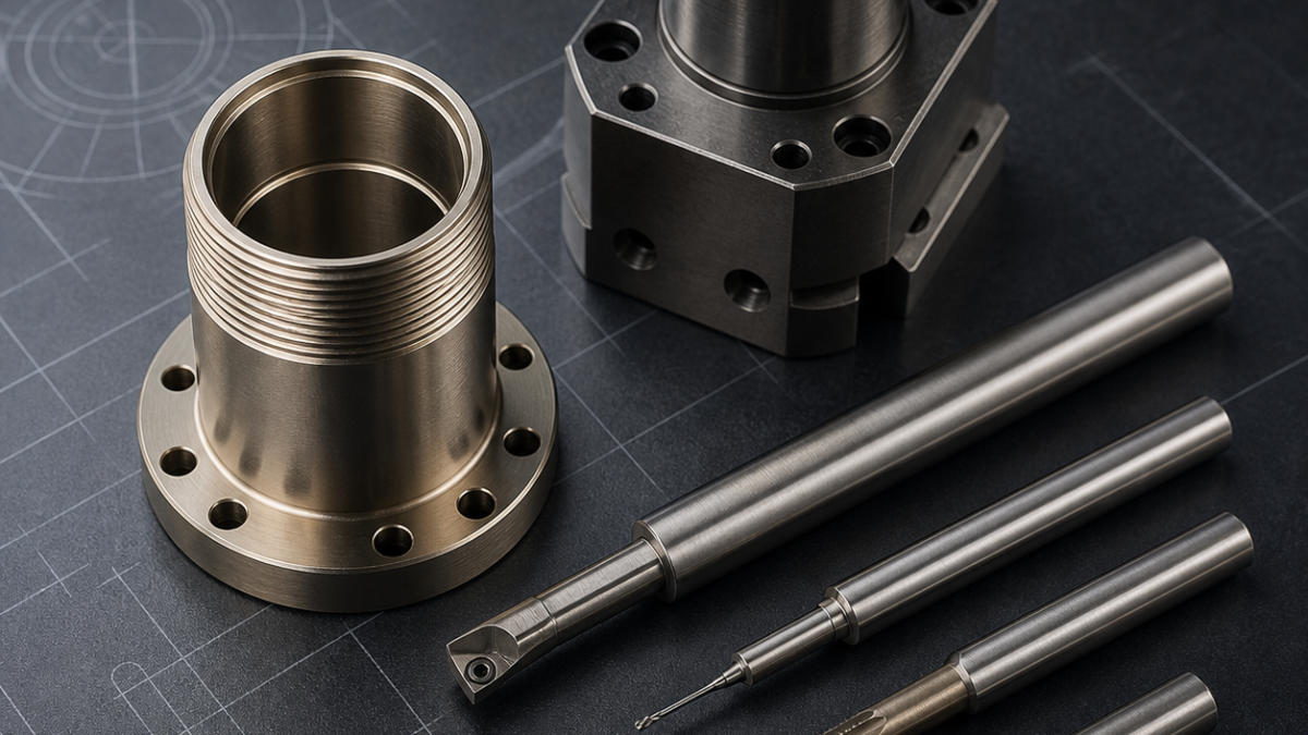
This is a hypothetical drawing-based process study, not a claim about a customer project or verified production result.
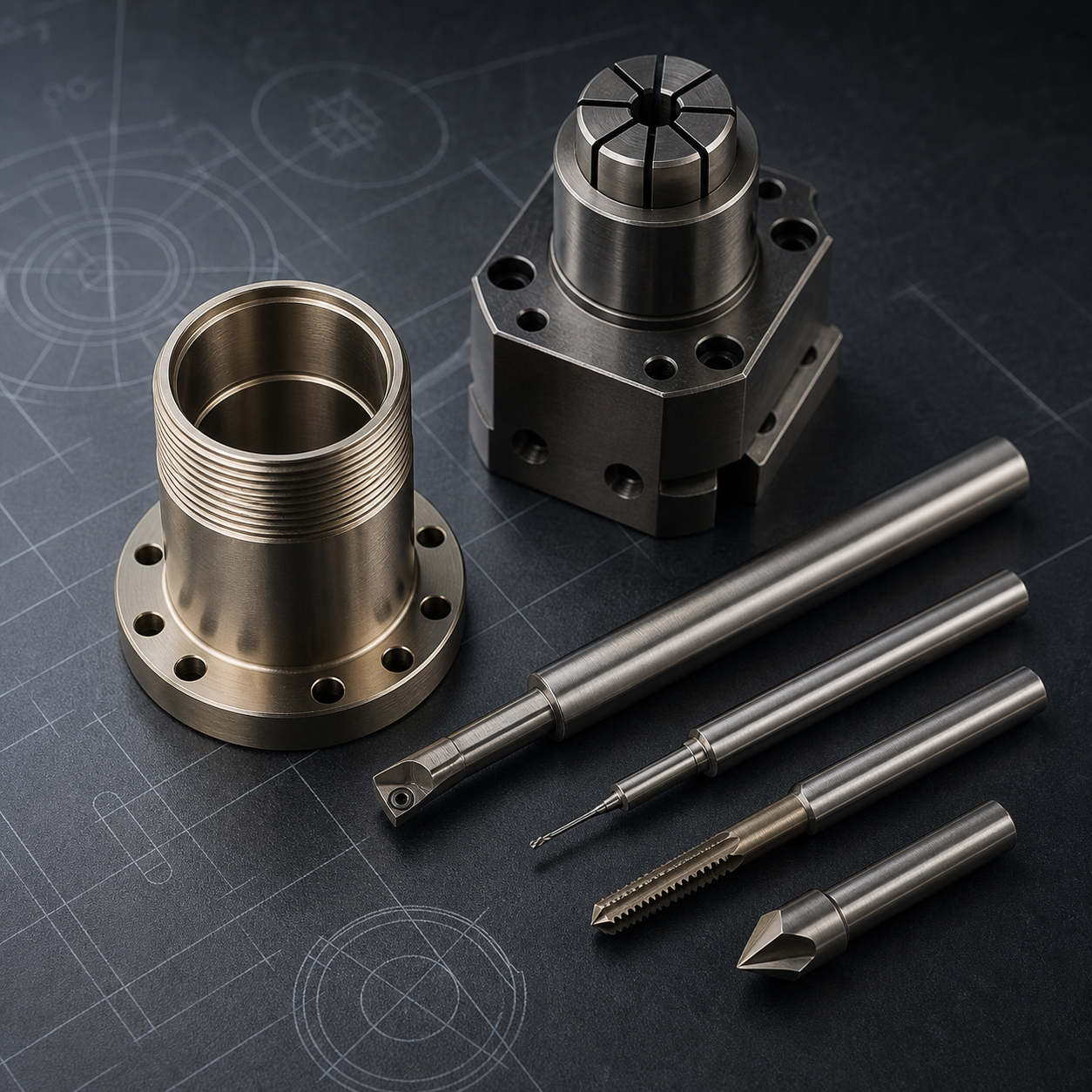
English: Kovar Single Feedthrough Shell CNC Tooling for Glass-Seal Bore and Fine Thread
For the search intent “single feedthrough Kovar,” the useful answer is a coaxial process, not a generic nickel-alloy recipe. This hypothetical shell keeps the glass-seal bore, M12×0.5 external thread and flange sealing face on one datum axis while temporary internal stock prevents the 0.6 mm wall from becoming oval under the collet.
Translate the drawing into a coaxial stack
Use the turned pilot as radial datum A and the flange back face as axial datum B. The glass-seal bore, thread pitch diameter and front sealing face form one functional stack; two clocking holes reference A-B rather than the raw OD. The hypothetical limits are 0.012 mm bore roundness after release, 0.02 mm face runout, Ra 0.4 micrometre on the seal face and a controlled 0.05–0.10 mm bore-edge break.
Keep support stock through thread generation
Start from annealed Kovar bar in a dead-length collet with pressure limited by a setup ring. A sharp 35-degree positive carbide insert with a thin low-friction PVD coating roughs the pilot, flange and OD. Drill the bore undersize with a short through-coolant carbide drill, then leave an internal support sleeve while a full-profile carbide threading insert generates M12×0.5 in modified-flank passes. A form tap is irrelevant and a die head applies excessive radial load.
Feature-to-tool map for a Kovar single feedthrough
| Drawing feature | Tool, geometry and holder | Selection logic / rejected alternative |
|---|---|---|
| Pilot, flange and OD roughing | 35° positive carbide insert, thin PVD coating, dead-length collet | Sharp shear limits work hardening; thick CVD edges push the wall. |
| Glass-seal bore pilot | Short 2-flute through-coolant carbide drill | Stable entry and chip evacuation; a long jobber drill wanders. |
| M12×0.5 external thread | Full-profile carbide insert, modified-flank infeed | Controls crest and radial load; die heads squeeze the shell. |
| Seal-bore finishing | 4 mm polished-rake micrograin carbide boring bar, minimum overhang | Corrects position and finish; spring passes rub and harden. |
| Clocking holes | 2.5 mm 2-flute carbide drill plus back-chamfer tool | Produces a measurable exit edge; manual picks scratch the flange. |
| Seal face and bore edge | Fresh positive facing insert plus 45° carbide chamfer mill | Separates face finish from edge break; abrasive paper rounds both. |
Finish the glass-seal bore with a different edge
After threading, transfer to a bored soft collet on the pilot. A 4 mm micrograin carbide boring bar with polished rake and minimal edge hone finishes the glass-seal bore in one continuous pass; repeated spring passes are rejected because rubbing work-hardens Kovar. A fine solid-carbide reamer is retained only when the pilot is already position-correct and the drawing accepts the resulting lay. The support sleeve is removed last with a sharp internal grooving tool.
Face, drill and deburr without moving the thin cylinder
With the pilot still supported, face the sealing land using a fresh positive insert from bore to OD so any burr is carried outward. The clocking holes use 2.5 mm two-flute carbide drills and a controlled back-chamfer tool. A 45-degree carbide chamfer mill creates the specified bore break; abrasive paper is rejected because it rounds the glass-seal edge and can embed contamination.
Use unclamped inspection as the release condition
Track built-up edge, spindle load and thread flank finish rather than tool time alone. Stop the boring tool when size drift or tearing appears and stop the thread tool at pitch-diameter trend or crest burr. Measure bore size and roundness after unclamping with low-force air or split-ball gauging, scan thread form optically, check face runout from datum A and record edge condition under magnification. Final cleaning and oxide preparation follow the qualified glass-sealing specification; machining dimensions alone do not prove hermeticity.
Related comparisons: Kovar multi-pin header tooling; C14500 RF feedthrough tooling; Kovar thin weld-rim tooling.
Practical FAQ
Why is the internal sleeve removed last? It carries collet and threading load while the wall is vulnerable.
Is honing automatically better for the glass-seal bore? No. Use it only when the drawing and sealing process qualify its lay, edge and cleanliness effects.
What distinguishes this from a multi-pin header? A single shell is controlled by one coaxial bore-thread-face stack; an array header is controlled primarily by pattern position and plate flatness.


