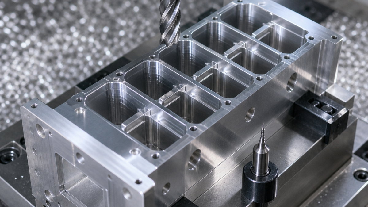
English: 7075-T651 Waveguide Filter CNC Tooling Case: Thin Iris Walls and Cavity Corners
For a 7075-T651 waveguide filter body, the drawing-to-tool decision is governed by the 1.0 mm iris walls and R0.6 cavity corners—not by the largest open pocket. This hypothetical case answers how to select carbide tools that rough quickly without bending the RF partitions, then finish the cavity geometry and sealing deck without burrs or tool-mark steps.

Drawing features and functional priorities
Datum A is the cover-seal deck, B and C are orthogonal dowel bores. Six stepped resonator cavities are 28 mm deep; iris thickness is 1.00 ±0.03 mm, corner radius R0.60 +0.05/0 mm, cavity profile 0.025 mm to A-B-C and deck flatness 0.020 mm at Ra 0.8 µm. RF performance depends on cavity width and iris location, while the outer block can tolerate a broader profile. Stock is stress-relieved before the thin separators are released.
Feature-to-tool selection
| Drawing feature | Selected tool | Reason and rejected alternative |
|---|---|---|
| Open cavity volume | Ø10 mm, 3-flute polished uncoated carbide, 35° helix, shrink holder | High chip space and sharp edge; a 4-flute coated steel tool packs aluminum chips. |
| Near-iris semifinish | Ø4 mm, 3-flute polished carbide, reduced neck, 18 mm reach | Short cutting length supports the wall; a long general-purpose cutter deflects. |
| R0.6 corners | Ø1.2 mm, 2-flute micro carbide, 6 mm flute, hydraulic micro chuck | Matches the radius with runout below 0.004 mm; EDM would add handoff and recast risk. |
| Seal deck | Ø40 mm PCD face mill with wiper insert | Stable Ra and low burr; a small end mill creates stitch marks. |
| Dowel bores | Carbide drill plus fine boring head | Boring corrects position; a reamer follows a displaced pilot. |
Toolpaths, fixture and material risks
Operation one machines A, rough dowel pilots and leaves 0.3 mm in cavities. Operation two locates A-B-C on a vacuum fixture with perimeter stops. Adaptive roughing opens alternate cavities so both sides of each iris retain similar stiffness. Near the wall, radial engagement falls below 8% of diameter. The Ø4 tool semifinishes both faces of an iris in alternating depth bands; the Ø1.2 tool only cleans corner residuals and never removes bulk stock.
Climb-only finish paths run from the wall root toward the supported perimeter. Air blast and minimum compatible lubricant prevent recutting. A rising spindle-load trend, white smeared edge or width drift indicates aluminum built-up edge. Tool length is measured warm, but cavity inspection occurs after thermal stabilization. Burrs receive a programmed 0.08 mm chamfer with a 90° polished carbide spot tool; hand scraping the iris is forbidden.
Inspection and search-focused FAQ
A CMM builds A-B-C, scans cavity widths at three depths, locates each iris center plane and measures corner radius. Optical measurement checks 1.0 mm walls without probe pressure. Deck flatness and Ra are verified after the final face pass; a cover-fit and leak-path check confirms sealing.
What end mill should finish a 1 mm waveguide iris?
Use the largest short, polished carbide tool that fits the adjacent geometry; here Ø4 mm finishes the faces, while Ø1.2 mm is reserved for R0.6 residuals.
Why not rough every cavity before finishing?
Alternating roughing retains balanced support on both sides of each thin partition.
How are RF cavity corners inspected?
Combine CMM profile scans with optical corner-radius measurement in the functional datum frame.
Related guidance: thin-wall pocket support and long-reach tool control.


