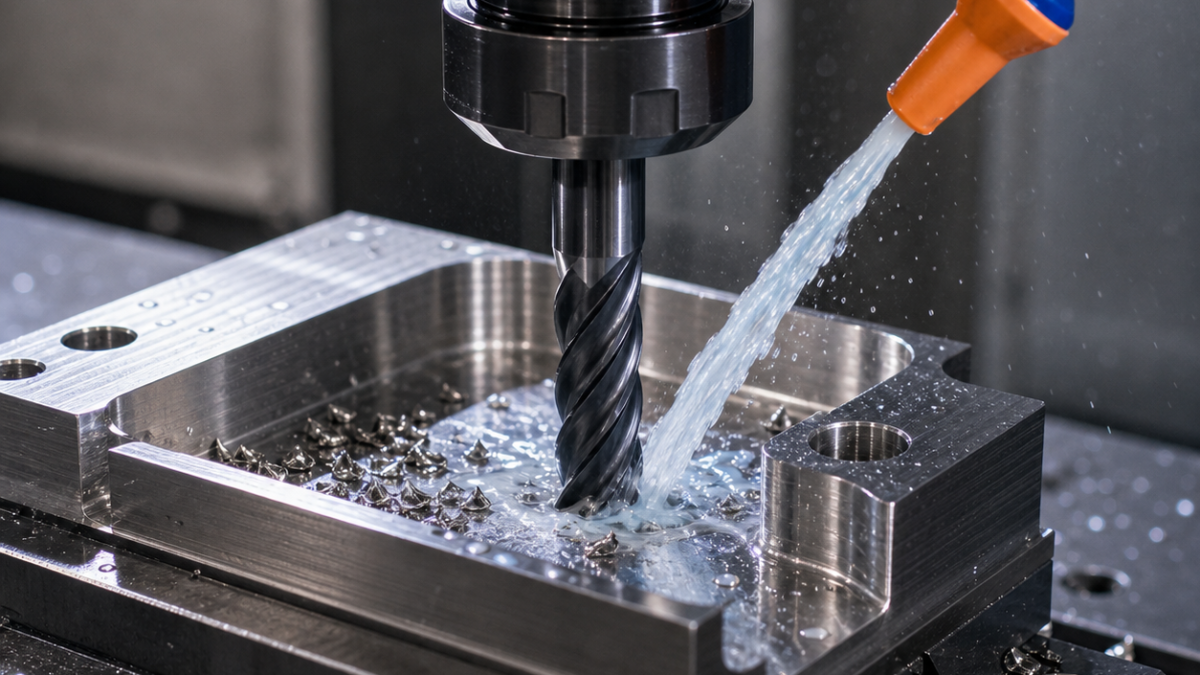
This is a hypothetical drawing-based technical study, not a claim about a customer project or verified production result.
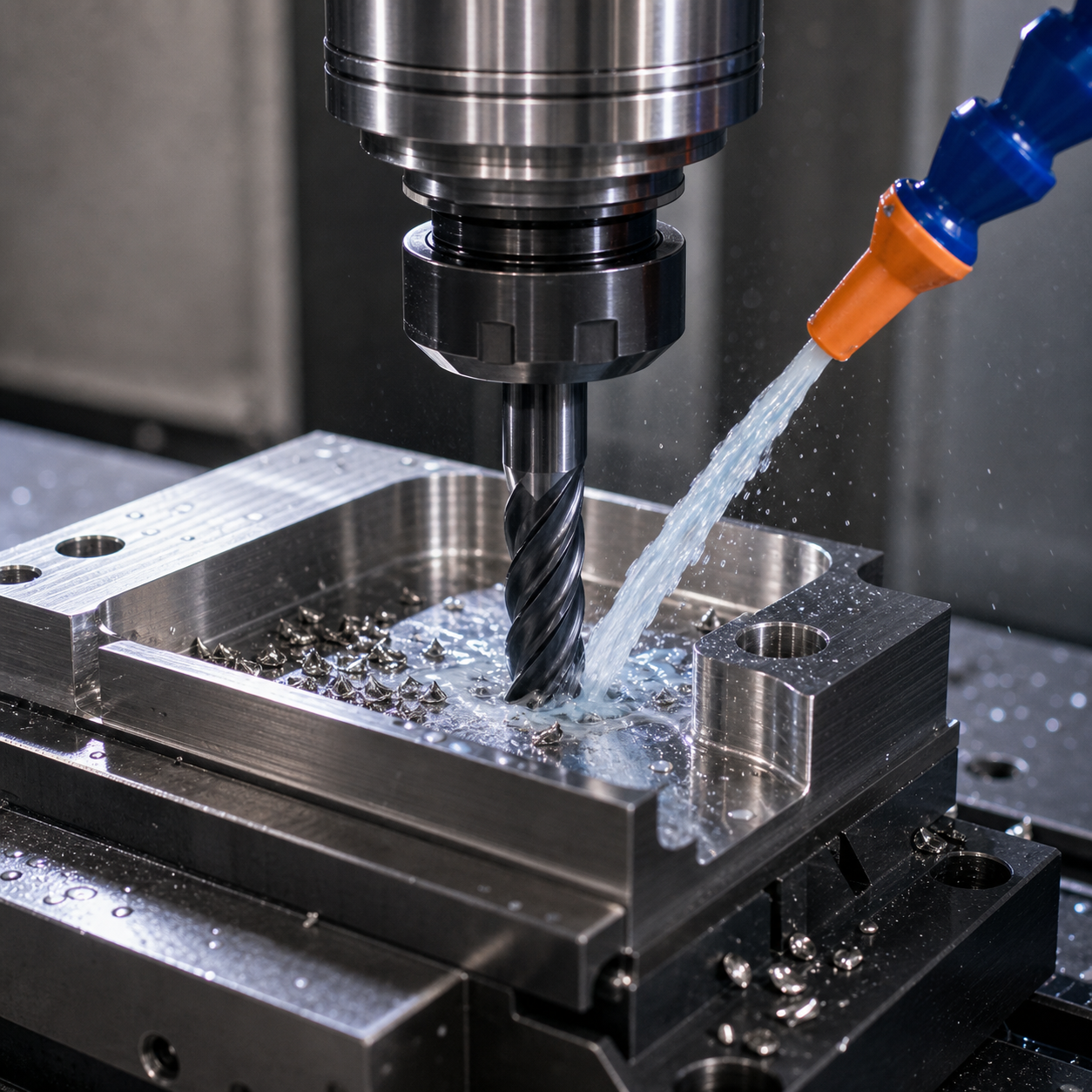
English: Stainless Steel CNC Milling Tool Selection to Prevent Work Hardening and Extend Tool Life
Preventing work hardening starts at the drawing, not at the override knob. Separate open pockets, full-width slots, thin walls, drilled intersections and threads because each changes edge engagement and chip exit. A hypothetical 316L manifold plate uses datum A, a 42 mm pocket, 8 mm slots, M6 ports and a 0.8 mm wall.
Feature-driven cutter choices
Use a 12 mm five-flute variable-helix carbide radius end mill with sharp positive geometry and a thin AlTiN/AlCrN PVD layer for adaptive pocket roughing. Select a 6 mm four-flute relieved-neck tool for slots and ribs, an 8 mm five-flute finisher for the datum wall, through-coolant carbide drills for ports, a thread mill for M6, and a small back-chamfer tool at intersections. A six-flute rougher is rejected because chip space collapses in a full slot; an HSS drill is rejected where heat and exit burr consistency dominate.
Cut continuously through the hardened skin
Establish datum A in soft jaws, rough pockets with constant radial engagement and programmed chip thinning, then semi-finish walls while the plate is supported. Avoid dwell and repeated spring passes. Apply climb milling, a positive entry arc and feed high enough for the edge to cut rather than rub. Finish thin walls in alternating depth bands, leaving symmetric stock, and open cross holes before the final sealing-wall pass.
Coolant, burr and tool-life gates
Aim through-tool coolant into the chip gullet. Peck only when hole depth and chip packing demand it; needless full retracts let the next entry strike a hardened band. Watch notch wear at the depth-of-cut line, edge buildup, spindle-load trend and wall-size correction. Change the rougher when notch growth forces compensation, not after catastrophic chipping. Back-chamfer internal exits and inspect by borescope; hand scraping is not a controlled substitute.
Inspect what the process can damage
Probe datum, pocket center and wall stock before release. Verify slot width with calibrated pins or CMM, thin-wall profile after unclamping, thread pitch diameter with the specified gauge, and burr condition under magnification. Surface finish is checked along the functional feed direction. Record grade and heat condition because 304, 316L and precipitation-hardening stainless do not share one parameter window.
| Drawing feature | Carbide tool and holder | Why / rejection |
|---|---|---|
| Open pocket / 开放型腔 | 12 mm, 5-flute variable-helix radius carbide; PVD; shrink-fit | Constant engagement; six flutes rejected for chip space |
| Full slot / 满槽 | 6 mm, 4-flute relieved-neck carbide; hydraulic holder | Chip room and reach; long general tool rejected |
| Datum wall / 基准壁 | 8 mm, 5-flute sharp finisher; low-runout holder | Dedicated edge avoids roughing notch wear |
| Ports and threads / 孔与螺纹 | Through-coolant carbide drill, thread mill, back chamfer | Controlled exit and recoverable thread size |
Related technical cases: stainless valve-body tooling; Nitronic 60 sleeve tooling; super-duplex impeller tooling.
FAQ
Why does stainless/titanium fail after a pause? The edge rubs or re-enters a heat-affected/work-hardened band instead of taking a stable chip.
How should tool life be ended? Use a defined wear, load, size-correction or surface trend, before unpredictable chipping.


