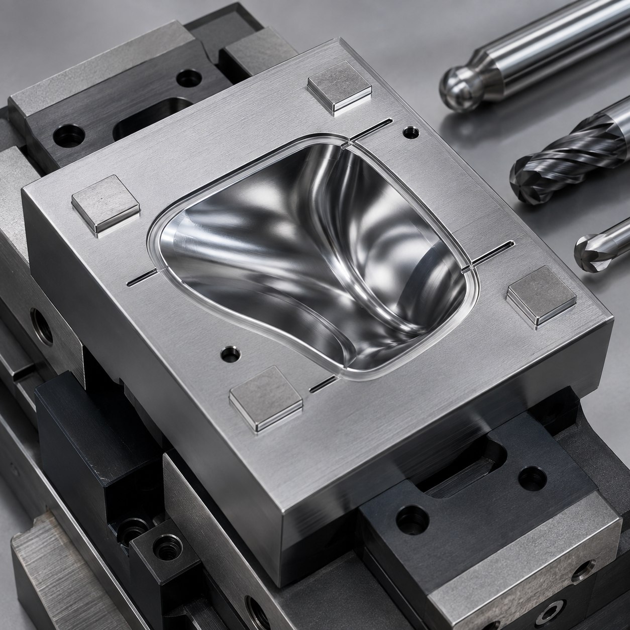
English: NAK80 Optical Mold Insert Tooling
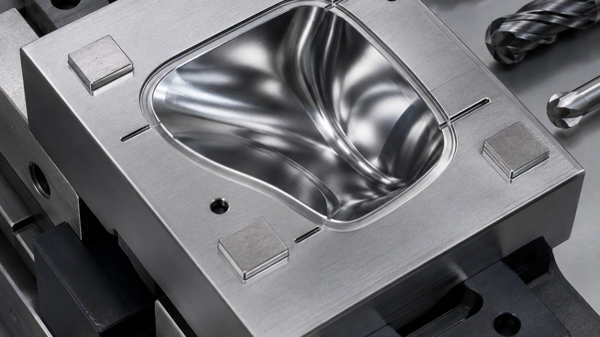
This search-focused case explains how a prehardened NAK80 mold drawing changes cutter choice when a freeform optical cavity meets a narrow flash land and micro vents. The decision is driven by cutter runout, reachable curvature, polishing stock and vent depth—not by a generic mold-steel recipe.
Drawing decisions
| Drawing zone | Selected carbide tool | Why and rejected alternative |
|---|---|---|
| Freeform cavity | Ø10 variable-helix 4-flute AlTiN carbide rougher, Ø3 ball-nose finisher | Short rougher removes bulk; ball tool follows curvature without faceting. |
| Flash land | Ø2 corner-radius carbide, 2 flutes, 6 mm reach in shrink-fit holder | Low runout protects land width; a sharp square tool is rejected for edge chipping. |
| Micro vents | Ø0.4 uncoated carbide slot cutter with polished flutes | Sharp edge limits ploughing; EDM is reserved only if cutter access fails. |
| Undercut relief | Ø4 lollipop carbide tool, AlCrN, reduced neck | Reaches behind shoulder while keeping the holder clear. |
| Datum pads | Ø16 fine-pitch face mill then wiper insert pass | Creates a stable reference before cavity inspection. |
Process, roughing and finishing
Probe datum pads, adaptive-rough with constant engagement, leave 0.20 mm on the freeform surface, semi-finish with a larger ball tool, then finish by curvature-limited scallop passes. Machine vents after polishing stock is verified. Control heat with filtered coolant and replace the ball tool when radius wear changes cusp height. Related reading: tool-overhang control and precision bore finishing.
Inspection and tool-life gate
CMM samples freeform deviation and flash-land width; an optical profilometer checks scallop height and vent floors. Verify Ra 0.4 µm before hand polishing, preserve 0.03 mm polishing allowance, blue-check the split line and inspect every vent under magnification.
Practical FAQ
Why is the smallest tool not used for the whole feature?
A larger rigid cutter removes stock and controls heat; the small tool is reserved for access-limited finishing.
When should an offset be changed?
Only after measurements show a stable directional error rather than changing deflection or edge wear.
What releases the part?
Functional geometry, surface finish, burr condition and datum relationships must all pass inspection.
中文: NAK80光学模芯自由曲面、飞边台与微排气槽配刀
本案例围绕图纸特征逐项配刀,并把刚性、伸出、刃口、涂层、夹具和检测作为一个完整决策链。
图纸特征配刀表
| 图纸区域 | 选择刀具 | 原因与替代方案 |
|---|---|---|
| Freeform cavity | Ø10 variable-helix 4-flute AlTiN carbide rougher, Ø3 ball-nose finisher | Short rougher removes bulk; ball tool follows curvature without faceting. |
| Flash land | Ø2 corner-radius carbide, 2 flutes, 6 mm reach in shrink-fit holder | Low runout protects land width; a sharp square tool is rejected for edge chipping. |
| Micro vents | Ø0.4 uncoated carbide slot cutter with polished flutes | Sharp edge limits ploughing; EDM is reserved only if cutter access fails. |
| Undercut relief | Ø4 lollipop carbide tool, AlCrN, reduced neck | Reaches behind shoulder while keeping the holder clear. |
| Datum pads | Ø16 fine-pitch face mill then wiper insert pass | Creates a stable reference before cavity inspection. |
工艺、粗精加工与排屑
Probe datum pads, adaptive-rough with constant engagement, leave 0.20 mm on the freeform surface, semi-finish with a larger ball tool, then finish by curvature-limited scallop passes. Machine vents after polishing stock is verified. Control heat with filtered coolant and replace the ball tool when radius wear changes cusp height. Related reading: tool-overhang control and precision bore finishing.
检验与刀具寿命
CMM samples freeform deviation and flash-land width; an optical profilometer checks scallop height and vent floors. Verify Ra 0.4 µm before hand polishing, preserve 0.03 mm polishing allowance, blue-check the split line and inspect every vent under magnification.
常见问题
为什么不能一把刀加工全部特征?
大刀负责稳定去除,小刀只用于受限区域,可减少挠曲和异常磨损。
什么时候能改刀补?
只有误差方向和大小稳定时才改;持续变化说明挠曲、热漂移或磨损。
最终放行看什么?
尺寸、基准关系、粗糙度、毛刺和通道清洁度必须同时合格。
Français: Outils NAK80 pour empreinte optique et micro-évents
Cette étude relie chaque fonction du plan au diamètre, à la géométrie, au revêtement et au porte-outil adaptés, puis valide le résultat par mesure.
Choix selon le plan
| Zone du plan | Outil retenu | Motif et alternative écartée |
|---|---|---|
| Freeform cavity | Ø10 variable-helix 4-flute AlTiN carbide rougher, Ø3 ball-nose finisher | Short rougher removes bulk; ball tool follows curvature without faceting. |
| Flash land | Ø2 corner-radius carbide, 2 flutes, 6 mm reach in shrink-fit holder | Low runout protects land width; a sharp square tool is rejected for edge chipping. |
| Micro vents | Ø0.4 uncoated carbide slot cutter with polished flutes | Sharp edge limits ploughing; EDM is reserved only if cutter access fails. |
| Undercut relief | Ø4 lollipop carbide tool, AlCrN, reduced neck | Reaches behind shoulder while keeping the holder clear. |
| Datum pads | Ø16 fine-pitch face mill then wiper insert pass | Creates a stable reference before cavity inspection. |
Gamme, ébauche et finition
Probe datum pads, adaptive-rough with constant engagement, leave 0.20 mm on the freeform surface, semi-finish with a larger ball tool, then finish by curvature-limited scallop passes. Machine vents after polishing stock is verified. Control heat with filtered coolant and replace the ball tool when radius wear changes cusp height. Related reading: tool-overhang control and precision bore finishing.
Contrôle et durée de vie
CMM samples freeform deviation and flash-land width; an optical profilometer checks scallop height and vent floors. Verify Ra 0.4 µm before hand polishing, preserve 0.03 mm polishing allowance, blue-check the split line and inspect every vent under magnification.
Questions pratiques
Why is the smallest tool not used for the whole feature?
A larger rigid cutter removes stock and controls heat; the small tool is reserved for access-limited finishing.
When should an offset be changed?
Only after measurements show a stable directional error rather than changing deflection or edge wear.
What releases the part?
Functional geometry, surface finish, burr condition and datum relationships must all pass inspection.
Русский: Инструмент NAK80 для оптической формы
Разбор связывает элементы чертежа с диаметром, геометрией, покрытием, вылетом и держателем инструмента, а затем с контролем.
Выбор по чертежу
| Зона чертежа | Выбранный инструмент | Причина выбора |
|---|---|---|
| Freeform cavity | Ø10 variable-helix 4-flute AlTiN carbide rougher, Ø3 ball-nose finisher | Short rougher removes bulk; ball tool follows curvature without faceting. |
| Flash land | Ø2 corner-radius carbide, 2 flutes, 6 mm reach in shrink-fit holder | Low runout protects land width; a sharp square tool is rejected for edge chipping. |
| Micro vents | Ø0.4 uncoated carbide slot cutter with polished flutes | Sharp edge limits ploughing; EDM is reserved only if cutter access fails. |
| Undercut relief | Ø4 lollipop carbide tool, AlCrN, reduced neck | Reaches behind shoulder while keeping the holder clear. |
| Datum pads | Ø16 fine-pitch face mill then wiper insert pass | Creates a stable reference before cavity inspection. |
Черновая и чистовая обработка
Probe datum pads, adaptive-rough with constant engagement, leave 0.20 mm on the freeform surface, semi-finish with a larger ball tool, then finish by curvature-limited scallop passes. Machine vents after polishing stock is verified. Control heat with filtered coolant and replace the ball tool when radius wear changes cusp height. Related reading: tool-overhang control and precision bore finishing.
Контроль и ресурс инструмента
CMM samples freeform deviation and flash-land width; an optical profilometer checks scallop height and vent floors. Verify Ra 0.4 µm before hand polishing, preserve 0.03 mm polishing allowance, blue-check the split line and inspect every vent under magnification.
Вопросы
Why is the smallest tool not used for the whole feature?
A larger rigid cutter removes stock and controls heat; the small tool is reserved for access-limited finishing.
When should an offset be changed?
Only after measurements show a stable directional error rather than changing deflection or edge wear.
What releases the part?
Functional geometry, surface finish, burr condition and datum relationships must all pass inspection.