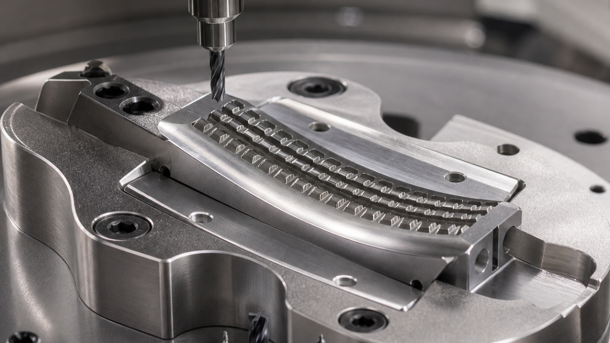
English: MP35N Stapler Anvil CNC Tool Selection for 0.45 mm Micro Pockets
For a hypothetical MP35N stapler anvil, micro-tool runout decides the pocket result before feed rate does. The curved forming face is first stabilized with a Ø3 bull nose, then each small staple pocket is opened by a Ø0.45 coated carbide cutter held below 0.003 mm runout. Serrations, hinge slot and locating holes use separate tools so a worn edge never transfers work-hardened stock into the pocket array.
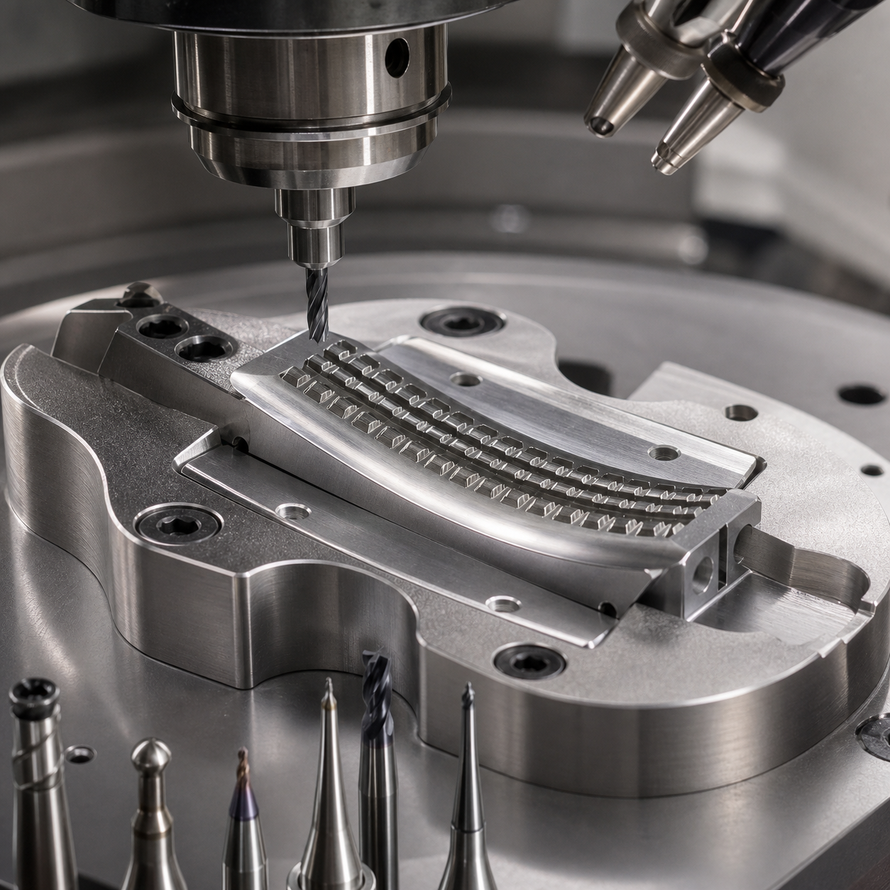
Drawing logic and the first-article gate
Curved face A, hinge bore B and side plane C define the array. Forty-eight hypothetical pockets are 0.55 mm wide, 0.32 mm deep and positioned within 0.020 mm; the face profile is 0.025 mm with Ra 0.4 µm. Serrations are 0.40 mm pitch and the hinge slot is 1.8 mm wide. The first three pockets form a release gate: they are inspected before the remaining array is machined.
Micro-tool map
| Feature | Selected carbide tool and holder | Control point |
|---|---|---|
| Forged blank roughing | Ø6 five-flute variable-pitch AlTiN micrograin carbide, R0.3, hydraulic holder | Adaptive path at low radial engagement; dedicated edge never enters micro pockets. |
| Curved face semifinish | Ø3 five-flute TiAlN bull nose R0.3, 12 mm reach, shrink holder | Leaves 0.08 mm normal stock with stable cusp. |
| Curved face finish | Ø2 four-flute AlCrN ball nose R1, polished flute, runout below 0.004 mm | Finishes along the forming direction without dwell. |
| Staple pockets | Ø0.45 two-flute AlTiN carbide, 1.2 mm cut, reinforced 0.01 mm edge, ultra-precision shrink holder | One helical entry and one finish orbit; tool is indexed by measured pocket count. |
| Fine serrations | Ø0.35 two-flute coated carbide slot tool, 0° helix, 0.8 mm cut | Straight flute limits lateral pull; a form cutter would load several teeth. |
| Hinge slot | Ø1.5 four-flute AlTiN end mill, necked 6 mm, hydraulic micro chuck | Trochoidal roughing and two compensated walls. |
| Locating holes | Ø1.8 through-coolant carbide drill, 140° point, followed by micro boring | Boring restores B position instead of relying on drill drift. |
Fixture and tool-life decisions
A contoured vacuum-assisted nest supports the back of A; two low clamps act outside the array. The face is semi-finished, thermalized and probed before the first three pockets. If their width, depth or corner condition fails, the runout, spindle growth and edge are corrected before release. The array proceeds in short blocks alternating left and right so heat does not walk along the curve.
MP35N work hardens when a micro cutter rubs. Every pocket entry remains in uncut stock, feed is maintained through arcs, and high-pressure filtered coolant reaches the active flute. A load increase, pocket-width drift or bright burnished floor retires the tool. No spring pass is allowed in the micro pockets.
Inspection and FAQ
White-light or qualified optical metrology measures pocket width, depth, corner and array position without probe force. A CMM checks A-B-C, hinge slot and bore; surface profilometry follows the curved forming direction. Final cleaning verifies no trapped microchips.
What runout is acceptable for a 0.45 mm pocket mill?
This route sets a process limit below 0.003 mm; the qualified limit must come from tool diameter, edge load and capability data.
Why inspect the first three pockets?
They reveal runout, thermal growth and work-hardening before the full array consumes tool life.
Why reject a spring pass in MP35N pockets?
A lightly loaded edge can rub and harden the floor, increasing wear without predictable size correction.
Compare medical micro-feature heat control and curved-face nickel-alloy tooling.
中文: MP35N吻合器抵钉座配刀:微小钉槽与曲面成形区
MP35N抵钉座加工中,微刀具跳动比单纯进给值更早决定钉槽质量。先用Ø3牛鼻刀稳定曲面余量,再以跳动低于0.003 mm的Ø0.45涂层硬质合金刀逐槽加工;细齿、铰链槽和定位孔各用专刀,防止磨损刃口把硬化层带入阵列。
首件放行
A曲面、B铰孔和C侧面定义48个假设钉槽。槽宽0.55 mm、深0.32 mm、位置度0.020 mm,曲面轮廓度0.025 mm、Ra 0.4 µm,细齿节距0.40 mm,铰链槽宽1.8 mm。前三个槽必须测量合格后才释放全阵列。
微刀具配刀表
| 特征 | 刀具 | 控制点 |
|---|---|---|
| 毛坯开粗 | Ø6五刃变齿AlTiN细晶刀,R0.3,液压刀柄 | 小径向动态刀路,严禁进入微槽。 |
| 曲面半精 | Ø3五刃TiAlN牛鼻刀R0.3,悬伸12 mm,热缩 | 均匀留法向0.08 mm。 |
| 曲面精加工 | Ø2四刃AlCrN球刀R1,抛光槽,跳动小于0.004 mm | 沿成形方向不停顿精刀。 |
| 钉槽 | Ø0.45两刃AlTiN,刃长1.2 mm,0.01 mm强化刃,超精热缩 | 一次螺旋进入和一次精圆周,按槽数管寿命。 |
| 细齿 | Ø0.35两刃涂层直槽刀,刃长0.8 mm | 直槽减小侧拉,多齿成形刀负载过大。 |
| 铰链槽 | Ø1.5四刃AlTiN缩颈刀,6 mm,液压微夹头 | 摆线开粗后两壁补偿。 |
| 定位孔 | Ø1.8内冷140°硬质合金钻+微镗 | 微镗恢复B位置。 |
装夹与刀寿
随形真空辅助软座支承A背面,低夹紧点避开阵列。半精、热稳定和探测后先加工三个槽;宽度、深度或角部不合格时,先修跳动、主轴热伸长和刃口再放行。阵列左右交替分块加工。
微刀必须从未切材料进入并保持圆弧进给,高压过滤冷却对准刃口。负载、槽宽漂移或发亮槽底触发换刀,禁止弹簧刀摩擦硬化。
检验与问题
白光或合格光学系统无接触测槽宽、深度、角部和位置;三坐标测A-B-C、铰链槽和孔,曲面粗糙度沿成形方向测。
Ø0.45刀跳动控制多少?
本例过程限值低于0.003 mm,正式限值应由能力数据确定。
为什么先测三个槽?
在消耗全阵列前识别跳动、热伸长和硬化。
为何不用弹簧刀?
轻载刃口会摩擦硬化槽底。
Français: Choix d’outils CNC pour enclume MP35N : micropoches de 0,45 mm
Le faux-rond gouverne les micropoches. Une torique Ø3 stabilise la face, puis Ø0,45 usine les logements sous 0,003 mm de faux-rond. Les stries et la charnière gardent leurs outils dédiés.
Table outil–fonction
| Fonction | Outil | Contrôle |
|---|---|---|
| Ébauche | Ø6, cinq dents variables AlTiN, R0,3 | Faible engagement radial. |
| Semi-finition | Torique Ø3 TiAlN, R0,3 | Réserve normale 0,08 mm. |
| Face | Boule Ø2, quatre dents AlCrN, R1 | Faux-rond <0,004 mm. |
| Poches | Ø0,45, deux dents AlTiN, coupe 1,2 mm | Entrée hélicoïdale et orbite finale. |
| Stries | Ø0,35, deux dents droites | Faible traction latérale. |
| Charnière | Ø1,5, quatre dents AlTiN, col 6 mm | Deux parois compensées. |
| Trous | Foret Ø1,8 puis micro-alésage | Position B restaurée. |
Libération et mesure
Un nid conforme soutient A. Trois poches sont mesurées avant la série; les blocs alternent gauche et droite. Charge, largeur ou fond bruni arrêtent l’outil, sans passe à vide.
La métrologie optique mesure les poches; la MMT contrôle A-B-C.
Quel faux-rond?
Ici moins de 0,003 mm.
Pourquoi trois poches?
Pour détecter chaleur et usure tôt.
Pourquoi pas de passe à vide?
Elle écrouit le fond.
Voir les microfonctions médicales et les faces courbes nickel.
Русский: Подбор CNC-инструмента MP35N: микрокарманы 0,45 мм
Биение определяет карманы. Тороидальная Ø3 стабилизирует поверхность, затем Ø0,45 обрабатывает ячейки при биении ниже 0,003 мм. Насечки и шарнир имеют отдельные инструменты.
Таблица инструментов
| Функция | Инструмент | Контроль |
|---|---|---|
| Черновая | Ø6, пять переменных зубьев AlTiN, R0,3 | Малое радиальное зацепление. |
| Полуфиниш | Тороидальная Ø3 TiAlN, R0,3 | Припуск 0,08 мм. |
| Поверхность | Шаровая Ø2 AlCrN, R1 | Биение <0,004 мм. |
| Карманы | Ø0,45, два зуба AlTiN | Винтовой вход и орбита. |
| Насечки | Ø0,35, два прямых зуба | Малая боковая сила. |
| Шарнир | Ø1,5, четыре зуба AlTiN | Компенсация стенок. |
| Отверстия | Сверло Ø1,8 и микрорасточка | Исправляет B. |
Выпуск и измерение
Контурное гнездо поддерживает A. Первые три кармана проверяют до массива. Рост нагрузки, ширины или блестящий пол останавливают инструмент; пружинный проход запрещён.
Оптика измеряет карманы, КИМ — A-B-C.
Какое биение?
Здесь ниже 0,003 мм.
Зачем три кармана?
Для раннего контроля тепла и износа.
Почему без холостого прохода?
Он наклёпывает дно.


