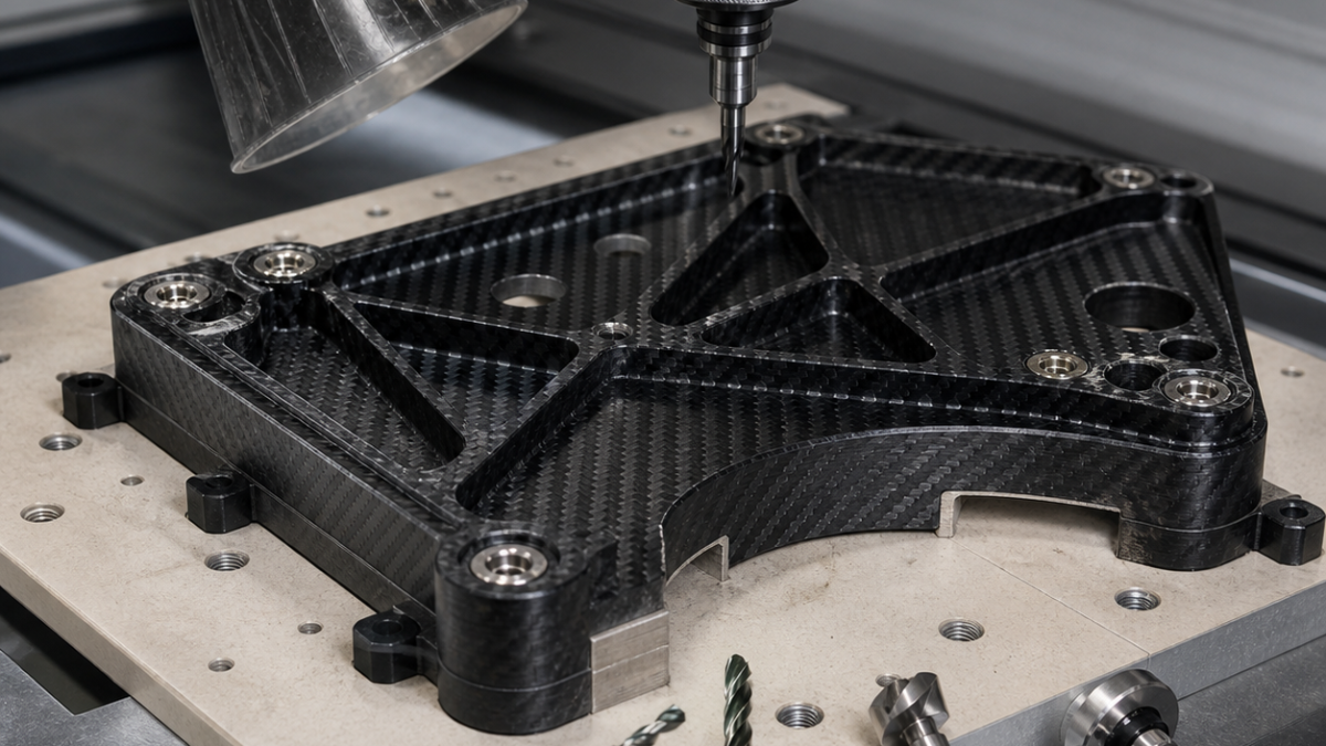
English: CFRP Bracket CNC Tool Selection for Insert Bores and 100° Countersinks
A cured CFRP optical-bench bracket should not use one cutter across laminate, adhesive and metal inserts. The reliable plan routes free laminate edges with a PCD compression tool, drills backed fastener holes with diamond-coated carbide, and finishes bonded datum inserts with a separate sharp carbide boring tool after probing. This hypothetical case keeps abrasive carbon dust away from the metallic-bore finish while protecting the countersink plies.
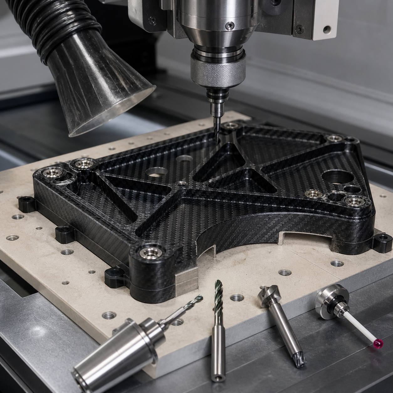
Datum logic at the laminate–insert boundary
Three bonded inserts define A-B-C; the trimmed outer profile is 0.15 mm to that frame. Two insert bores are Ø10 H7 and coaxial within 0.025 mm, six fasteners use a drawing-specific 100° countersink, and a 4 mm cable relief runs along a rib. Countersink breakout, loose fibers and resin whitening are prohibited in the inspection zone. Because cured laminate thickness varies locally, the probe measures insert faces and four skin pads before Z depths are released.
Feature-to-tool selection
| Drawing zone | Tool and holder | Selection logic |
|---|---|---|
| Free outer edge | Ø8 two-edge PCD compression router, 18 mm cut, precision collet | Opposed cutting action contains top and bottom plies; a conventional upcut tool lifts the top skin. |
| Rib relief | Ø4 two-flute diamond-coated carbide, low 20° helix, 10 mm cut, hydraulic micro chuck | Short reach controls the narrow rib; long high-helix geometry increases peel force. |
| Fastener pilot | Ø4.8 diamond-coated carbide brad-point drill, double margin, minimum projection | The outside spurs sever fibers before the core; a standard 118° drill pushes an exit cone. |
| 100° countersink | Ø12 PCD countersink, three cutting sectors, zero-rake land, preset holder | Low axial force and stable angle; a multi-flute HSS tool dulls quickly in carbon. |
| Bonded insert bore | Ø8.5 carbide drill followed by positive micrograin-carbide fine boring head R0.2 | Boring corrects insert position; a reamer would follow the adhesive-shifted pilot. |
| Edge seal chamfer | Ø6 diamond-coated two-flute 90° tool, 0.10 mm programmed break | Creates a measurable edge before sealing; hand sanding rounds datum-adjacent zones. |
Fixture, sequence and contamination control
A vacuum fixture supports the skin on a sacrificial phenolic backer, while three mechanical stops contact only cured datum pads. Outer trimming proceeds climb-cut in two depth bands; the final 0.3 mm is removed toward supported material. Fastener holes are drilled through the backer, then countersunk from the functional face with axial probing at every location. Dust extraction remains at the cutting point, and compressed-air dispersal is prohibited.
After laminate operations, the nest and spindle taper are cleaned under the approved composite-dust procedure. Only then are metal insert pilots and bores finished with dedicated tools. Rising spindle load, fuzzy exit fibers or a glossy rubbed edge are change signals. Tools used in metal never return to carbon, preventing abrasive contamination and unstable bore size.
Inspection and FAQ
A CMM builds A-B-C from insert faces and bores; optical inspection measures countersink diameter, ply condition and the cable-relief edge. Bore size is checked with an air gauge after thermal stabilization. A tap test or qualified NDI method examines suspect laminate, while cleanliness and edge sealing follow the drawing.
Which router prevents CFRP edge delamination?
A PCD compression router sized to keep both faces supported; here Ø8 uses opposing cutting action.
Why fine-bore bonded inserts instead of reaming?
Fine boring corrects actual insert position and diameter, whereas a reamer follows the displaced pilot.
How are CFRP countersinks kept clean?
Back the laminate, probe local thickness, use a sharp PCD countersink and stop at the measured diameter rather than a fixed depth.
Related reading: diamond tooling for composite holes and datum-sensitive aerospace pocket tooling.
中文: CFRP光学支架CNC配刀:嵌件孔、100°沉头孔与防分层
固化CFRP支架不能让同一把刀跨越层合板、胶层和金属嵌件。自由边用PCD压缩刃修边,带背衬的紧固孔用金刚石涂层硬质合金钻,嵌件在探测后另用锋利精镗刀完成,从而把碳粉与金属孔精加工隔离。
基准和局部厚度
三处粘接嵌件建立A-B-C,外轮廓对其0.15 mm;两孔Ø10 H7且同轴0.025 mm,六个紧固孔为图纸规定100°沉头,肋上有4 mm线缆让位。探针先测嵌件面和四个蒙皮点再释放Z深度。
特征—刀具表
| 区域 | 刀具 | 理由 |
|---|---|---|
| 自由边 | Ø8双刃PCD压缩铣刀,刃长18 mm,精密筒夹 | 上下相向切削压住两面,普通上旋刀会抬起上层。 |
| 肋让位 | Ø4两刃金刚石涂层硬质合金,20°低螺旋,刃长10 mm | 短悬伸降低剥离力。 |
| 紧固孔 | Ø4.8金刚石涂层硬质合金尖刃钻,双刃带 | 外缘先切断纤维,118°普通钻会推挤出口。 |
| 100°沉头 | Ø12三扇区PCD沉头刀,零前角刃带,预调刀柄 | 轴向力低并稳定角度。 |
| 嵌件孔 | Ø8.5硬质合金钻+R0.2正角细晶精镗头 | 精镗修正粘接偏位,铰刀只跟随预孔。 |
| 封边倒角 | Ø6两刃金刚石涂层90°刀,程序倒0.10 mm | 可测量,拒绝手工打磨基准邻区。 |
夹具与粉尘
真空夹具以牺牲酚醛背板支承蒙皮,机械挡块只接触固化基准垫。外形分两层顺铣,最后0.3 mm朝支承材料切;紧固孔贯穿背板,沉头逐孔探高。复材工序后按批准流程清洁夹具和主轴锥孔,再用专用金属刀具加工嵌件。
负载上升、出口纤维发毛或边缘发亮表示刀钝或摩擦。金属刀不得返回碳纤维工序。
检验与问题
三坐标由嵌件建立A-B-C,光学测沉头、铺层和让位边,气动量仪测孔。疑似分层按合格无损方法检查。
CFRP修边选什么刀?
能同时压住上下表层的Ø8 PCD压缩刃。
为何嵌件不用铰刀?
精镗可修实际孔位,铰刀跟随偏孔。
沉头怎样防分层?
背衬、逐孔测厚、锋利PCD刀并按实测直径停刀。
Français: Choix d’outils CNC pour support CFRP : alésages et fraisures à 100°
Le stratifié, l’adhésif et l’insert métallique reçoivent des outils distincts. Le PCD comprime les bords, le carbure diamanté perce sur support et l’alésage fin corrige les inserts sondés.
Table fonction–outil
| Zone | Outil | Choix |
|---|---|---|
| Contour | Routeur PCD compression Ø8, coupe 18 mm | Retient les deux plis extérieurs. |
| Relief | Carbure diamanté Ø4, deux dents, 20° | Faible effort de pelage. |
| Pilote | Foret diamanté Ø4,8 à pointe périphérique | Sectionne les fibres avant la sortie. |
| Fraisure | PCD Ø12 à 100°, trois secteurs | Angle stable et faible poussée. |
| Insert | Foret Ø8,5 puis alésage carbure R0,2 | Corrige la position collée. |
| Chanfrein | Ø6 diamanté, 90°, cassé 0,10 mm | Évite le ponçage manuel. |
Processus et contrôle
Le vide et un martyr phénolique soutiennent la peau. Chaque fraisure est sondée; l’aspiration reste au point de coupe. Après nettoyage composite, des outils dédiés finissent les inserts. Charge, fibres floues et bord lustré commandent le changement.
MMT, vision et jauge pneumatique vérifient bases, plis, fraisures et H7.
Quel routeur?
PCD compression Ø8.
Pourquoi aléser?
Pour corriger l’insert réel.
Comment protéger la fraisure?
Support, sondage et PCD vif.
Voir les trous composites et les bases aérospatiales.
Русский: Подбор CNC-инструмента для CFRP: вставки и зенковки
Ламинат, клей и металл требуют разных инструментов. PCD сжимает края, алмазное покрытие сверлит на подкладке, тонкая расточка исправляет положение вставок.
Таблица зона–инструмент
| Зона | Инструмент | Причина |
|---|---|---|
| Контур | Компрессионный PCD Ø8, длина 18 мм | Удерживает оба наружных слоя. |
| Выемка | Алмазное покрытие Ø4, два зуба, 20° | Малая сила расслоения. |
| Пилот | Алмазное сверло Ø4,8 с наружными резцами | Сначала режет волокна. |
| Зенковка | PCD Ø12, 100°, три сектора | Стабильный угол. |
| Вставка | Сверло Ø8,5 и карбидная расточка R0,2 | Исправляет смещение. |
| Фаска | Алмазная Ø6, 90°, 0,10 мм | Без ручного шлифования. |
Маршрут и контроль
Вакуум и фенольная подложка поддерживают деталь. Каждую зенковку измеряют щупом, пыль удаляют у резания. После очистки отдельные инструменты заканчивают металл. Нагрузка, пушистый выход и блеск задают смену.
КИМ, оптика и пневмокалибр проверяют базы, слои и H7.
Какая фреза?
Компрессионная PCD Ø8.
Зачем расточка?
Для коррекции вставки.
Как защитить зенковку?
Подкладкой, щупом и острым PCD.


