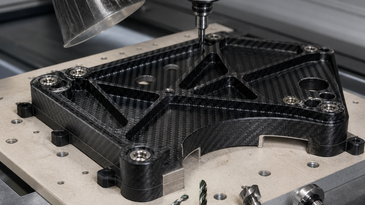
English: CFRP Bracket CNC Tool Selection for Insert Bores and 100° Countersinks
A cured CFRP optical-bench bracket should not use one cutter across laminate, adhesive and metal inserts. The reliable plan routes free laminate edges with a PCD compression tool, drills backed fastener holes with diamond-coated carbide, and finishes bonded datum inserts with a separate sharp carbide boring tool after probing. This hypothetical case keeps abrasive carbon dust away from the metallic-bore finish while protecting the countersink plies.
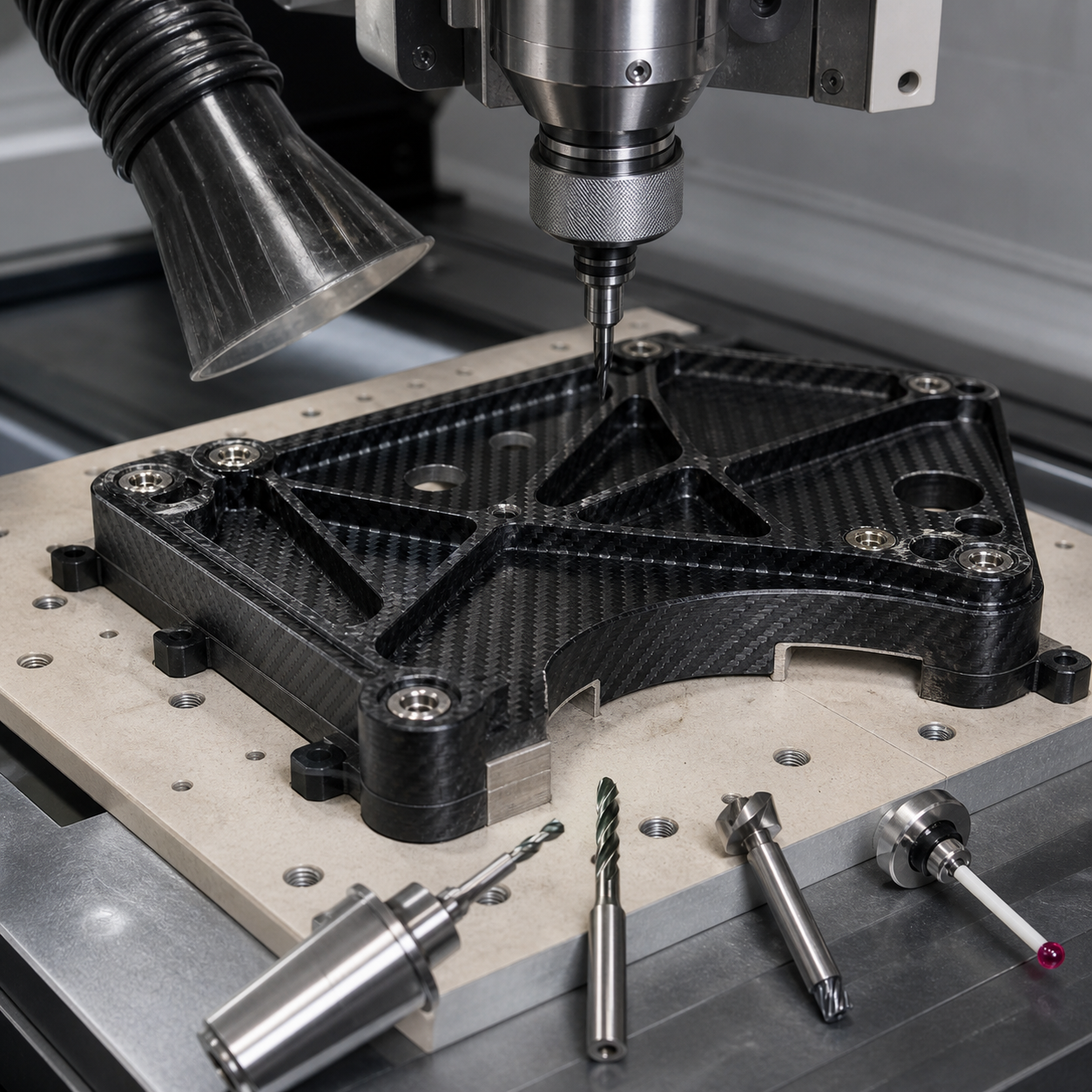
Datum logic at the laminate–insert boundary
Three bonded inserts define A-B-C; the trimmed outer profile is 0.15 mm to that frame. Two insert bores are Ø10 H7 and coaxial within 0.025 mm, six fasteners use a drawing-specific 100° countersink, and a 4 mm cable relief runs along a rib. Countersink breakout, loose fibers and resin whitening are prohibited in the inspection zone. Because cured laminate thickness varies locally, the probe measures insert faces and four skin pads before Z depths are released.
Feature-to-tool selection
| Drawing zone | Tool and holder | Selection logic |
|---|---|---|
| Free outer edge | Ø8 two-edge PCD compression router, 18 mm cut, precision collet | Opposed cutting action contains top and bottom plies; a conventional upcut tool lifts the top skin. |
| Rib relief | Ø4 two-flute diamond-coated carbide, low 20° helix, 10 mm cut, hydraulic micro chuck | Short reach controls the narrow rib; long high-helix geometry increases peel force. |
| Fastener pilot | Ø4.8 diamond-coated carbide brad-point drill, double margin, minimum projection | The outside spurs sever fibers before the core; a standard 118° drill pushes an exit cone. |
| 100° countersink | Ø12 PCD countersink, three cutting sectors, zero-rake land, preset holder | Low axial force and stable angle; a multi-flute HSS tool dulls quickly in carbon. |
| Bonded insert bore | Ø8.5 carbide drill followed by positive micrograin-carbide fine boring head R0.2 | Boring corrects insert position; a reamer would follow the adhesive-shifted pilot. |
| Edge seal chamfer | Ø6 diamond-coated two-flute 90° tool, 0.10 mm programmed break | Creates a measurable edge before sealing; hand sanding rounds datum-adjacent zones. |
Fixture, sequence and contamination control
A vacuum fixture supports the skin on a sacrificial phenolic backer, while three mechanical stops contact only cured datum pads. Outer trimming proceeds climb-cut in two depth bands; the final 0.3 mm is removed toward supported material. Fastener holes are drilled through the backer, then countersunk from the functional face with axial probing at every location. Dust extraction remains at the cutting point, and compressed-air dispersal is prohibited.
After laminate operations, the nest and spindle taper are cleaned under the approved composite-dust procedure. Only then are metal insert pilots and bores finished with dedicated tools. Rising spindle load, fuzzy exit fibers or a glossy rubbed edge are change signals. Tools used in metal never return to carbon, preventing abrasive contamination and unstable bore size.
Inspection and FAQ
A CMM builds A-B-C from insert faces and bores; optical inspection measures countersink diameter, ply condition and the cable-relief edge. Bore size is checked with an air gauge after thermal stabilization. A tap test or qualified NDI method examines suspect laminate, while cleanliness and edge sealing follow the drawing.
Which router prevents CFRP edge delamination?
A PCD compression router sized to keep both faces supported; here Ø8 uses opposing cutting action.
Why fine-bore bonded inserts instead of reaming?
Fine boring corrects actual insert position and diameter, whereas a reamer follows the displaced pilot.
How are CFRP countersinks kept clean?
Back the laminate, probe local thickness, use a sharp PCD countersink and stop at the measured diameter rather than a fixed depth.
Related reading: diamond tooling for composite holes and datum-sensitive aerospace pocket tooling.


