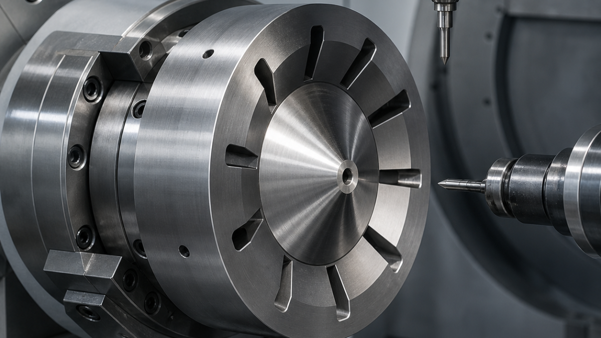
English: ARMCO Pure-Iron Pole Piece CNC Tool Selection for Air-Gap Cone and Radial Slots
An ARMCO pure-iron pole piece fails magnetically when machining leaves a raised burr on the air-gap face or shifts the narrow centre land, even if the outside diameter is correct. Pure iron tends to build up on a dull edge, so this hypothetical plan uses positive polished carbide for the cone, symmetrical slot release and demagnetized fixtures that do not hold chips against the finished pole face.
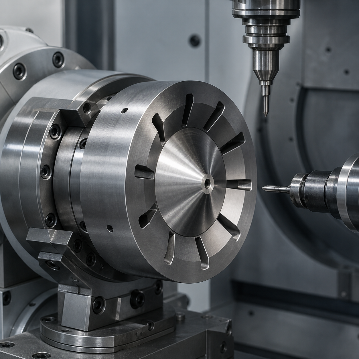
The magnetic surfaces define the machining frame
Mounting face A and centre bore B locate a 60° included air-gap cone C. Bore B is Ø20 H7; C runs true to B within 0.010 mm and finishes at Ra 0.4 µm. The central pole land is Ø8.00 +0.010/0 mm and 1.20 ±0.015 mm high. Eight radial coil-clearance slots are 2.00 +0.030/0 mm wide, 12 mm deep and terminate at R1.0, leaving a 1.00 mm magnetic bridge. Bolt-circle position is 0.030 mm. The drawing prohibits burrs leaning onto C and ferrous chips trapped in the slots.
Cone, pole land and bore are therefore finished in one spindle orientation. The radial slots are released in opposed pairs only after their roots are supported.
Feature-specific carbide selection
| Zone | Selected cutter and holder | Selection logic and rejection |
|---|---|---|
| Forged OD and back relief | Ø12 five-flute variable-pitch AlCrN micrograin-carbide end mill, 38° helix, R0.5, 0.025 mm edge hone, hydraulic chuck | The tough edge handles interrupted stock; an aluminium-grade razor edge chips at the scale boundary. |
| Centre bore Ø20 H7 | Ø17.5 three-flute through-coolant carbide drill, 140° point, followed by a positive polished R0.2 fine-boring insert on a short damped bar | Fine boring restores B axis and diameter; a reamer follows any drilling error. |
| Air-gap cone roughing | Ø10 five-flute AlTiN bull-nose carbide mill, R0.5, unequal pitch, 18 mm reach, shrink holder | Constant-engagement spiral leaves 0.08 mm normal stock; a ball mill adds unnecessary contact near the cone centre. |
| Cone C finishing | Ground DCGT 11T302 uncoated micrograin-carbide insert, 20° polished positive rake, R0.2, 0.005 mm edge hone, rigid dedicated tool block | Shears pure iron without built-up edge; a honed coated insert pushes a bright folded ridge. |
| Central pole land | Ø16 single-insert positive carbide sweep tool, polished uncoated R0.4 insert, balanced arbor | One outward pass avoids overlapping tracks on the magnetic face. |
| Radial slot roughing | Ø1.6 three-flute AlCrN carbide, 20° low helix, necked 10 mm, micro hydraulic chuck | Trochoidal path preserves the 1 mm bridge; full-width plunging work-hardens and bends the exit. |
| Slot wall finishing | Ø2.0 four-flute unequal-pitch AlCrN carbide, R0.1, 12 mm reach, minimum projection | Compensated passes size each wall; a 2 mm form plunge cannot correct taper. |
| Bolt holes and threads | Ø6.8 through-coolant carbide drill, 140°, then Ø5 five-flute AlCrN thread mill for M8×1.25 | Thread milling avoids tap seizure in smeared material and controls pitch diameter. |
Symmetric release and chip discipline
The forging is normalized according to the hypothetical process plan and verified demagnetized before setup. Operation one establishes A, B and back relief in soft jaws that contact only nonfunctional bands. The cone is semi-finished and probed, then B, C and the pole land receive their final cuts without changing the rotary datum.
A relieved backup ring supports the slot roots. Slots are opened 1–5, 3–7, 2–6, 4–8, with the Ø1.6 cutter leaving 0.10 mm per wall. Filtered flood coolant keeps chips away from C; compressed air is not directed across the pole face. After a short thermal pause, the Ø2 tool finishes from root to mouth. A silver smear, rising torque or burr leaning toward the cone retires the edge.
Inspection after demagnetization
A CMM establishes A-B and checks cone angle, pole height, bolt circle and slots. A roundness instrument verifies B and cone runout; a profilometer traces C along the generator. Optical inspection records burr direction and slot-root radius. The part is cleaned and demagnetized again before final measurement so retained chips cannot distort contact or contaminate the air gap.
What carbide geometry is suitable for ARMCO pure iron?
A micrograin insert with polished positive rake and a very small edge hone cuts the ductile metal before built-up edge forms.
Why machine radial slots in opposite pairs?
Opposed release balances compliance and prevents one side of the pole land moving before the others are opened.
Why demagnetize before inspection?
Residual attraction can retain fine chips on the air-gap cone and corrupt tactile or optical results.
Related process guidance: burr control on supported thin sections and fixture and chatter control for precision faces.
中文: ARMCO纯铁磁极件CNC配刀:气隙锥面与径向槽
ARMCO纯铁磁极件即使外径合格,只要气隙面有翻起毛刺或中心极面偏移,功能就会受影响。纯铁容易在钝刃上形成积屑瘤,因此本案例以抛光正前角硬质合金精锥面,径向槽成对对称释放,并要求夹具处于退磁状态,避免切屑吸附在完成面。
磁性功能面建立尺寸链
安装面A和Ø20 H7中心孔B定位60°夹角气隙锥面C。C对B跳动0.010 mm、Ra 0.4 µm;中心极面Ø8.00 +0.010/0 mm,高1.20 ±0.015 mm。八条线圈让位槽宽2.00 +0.030/0 mm、深12 mm、槽根R1.0,保留1.00 mm磁桥;螺栓圆位置度0.030 mm。图纸不允许毛刺倒向C面或铁屑留槽。
按功能区配刀
| 区域 | 刀具配置 | 选择理由 |
|---|---|---|
| 锻坯外圆和背腔 | Ø12五刃不等距AlCrN细晶硬质合金,38°,R0.5,刃口0.025 mm,液压刀柄 | 韧性刃承受断续氧化皮,铝用薄刃容易崩。 |
| Ø20 H7中心孔 | Ø17.5三刃内冷硬质合金钻、140°,随后R0.2抛光正角精镗片和短减振杆 | 精镗修正B轴线,铰刀跟随钻偏。 |
| 锥面开粗 | Ø10五刃不等分AlTiN圆鼻刀R0.5,悬伸18 mm,热缩柄 | 恒定吃刀法向留0.08 mm,球刀在中心接触过宽。 |
| C面精加工 | 精磨DCGT 11T302无涂层细晶硬质合金,20°抛光正前角,R0.2,刃口0.005 mm | 直接剪切纯铁,钝化涂层片会推出发亮卷边。 |
| 中心极面 | Ø16单刃正角硬质合金扫掠刀,抛光无涂层R0.4,平衡刀杆 | 一次向外切削,无多刀片接痕。 |
| 径向槽开粗 | Ø1.6三刃AlCrN,20°低螺旋,缩颈10 mm,微型液压柄 | 摆线开粗保护1 mm磁桥,拒绝满槽下压。 |
| 槽壁精加工 | Ø2.0四刃不等分AlCrN,R0.1,悬伸12 mm | 两壁分别补偿,成形下刀不能修锥度。 |
| M8孔 | Ø6.8内冷硬质合金钻+Ø5五刃AlCrN螺纹铣刀,M8×1.25 | 避免丝锥在涂抹层中咬死。 |
对称开槽与切屑管理
按假设工艺完成正火后,毛坯先确认退磁。第一序软爪只夹非功能带,建立A、B和背腔;锥面半精并探测后,不改变回转基准,连续精B、C和中心极面。避空背环支承槽根,开槽顺序为1–5、3–7、2–6、4–8,每壁留0.10 mm。
过滤冷却液把铁屑带离C面,不用压缩空气横扫完成面。热稳定后Ø2刀从槽根向出口精壁。银亮涂抹、扭矩上升或毛刺倒向锥面都表示刀具退出。
退磁后的检验与问题
三坐标建立A-B并测锥角、极面高度、螺栓圆和槽,圆度仪测B和锥跳,轮廓仪沿母线测C面。光学记录毛刺方向和槽根R;清洗、再次退磁后才做最终测量,避免吸附切屑干扰。
纯铁适合什么硬质合金刃形?
细晶基体、抛光正前角和极小刃口钝化,先剪切材料再阻止积屑瘤。
为什么径向槽要对称成对加工?
对称释放柔性,防止一侧先开后把中心极面推偏。
为什么检验前必须退磁?
残磁会吸附细小铁屑,影响气隙面接触和光学、接触测量。
参考:薄截面支承与毛刺控制、夹具刚性和振纹控制。
Français: Outils CNC pour pièce polaire ARMCO : cône d’entrefer et rainures
La fonction magnétique dépend du cône et du petit plot central, pas seulement du diamètre extérieur. Le fer pur colle sur une arête émoussée. Une géométrie carbure positive et polie, des rainures ouvertes par paires et un montage démagnétisé évitent bourrelet et copeaux retenus.
Surfaces fonctionnelles du plan
A et l’alésage B Ø20 H7 placent le cône C à 60°. C tourne à 0,010 mm et demande Ra 0,4 µm. Le plot est Ø8,00 +0,010/0 mm, hauteur 1,20 ±0,015 mm. Huit rainures font 2,00 +0,030/0 mm sur 12 mm, racine R1,0, pont magnétique 1,00 mm.
Outils par zone
| Zone | Outil | Choix |
|---|---|---|
| Brut | Ø12, cinq dents variables AlCrN, 38°, R0,5, arête 0,025 mm, hydraulique | Résiste à la peau interrompue. |
| B Ø20 H7 | Foret Ø17,5 arrosé à 140°, puis alésage fin positif R0,2 | Restaure axe et diamètre. |
| C ébauche | Torique Ø10, cinq dents AlTiN, R0,5, portée 18 mm | Réserve normale 0,08 mm. |
| C finition | DCGT 11T302 non revêtue, angle poli 20°, R0,2, préparation 0,005 mm | Coupe sans arête rapportée. |
| Plot | Monodent carbure poli, balayage Ø16, R0,4 | Une passe vers l’extérieur. |
| Rainure brute | Ø1,6, trois dents AlCrN, hélice 20°, col 10 mm | Trajectoire trochoïdale douce. |
| Parois | Ø2,0, quatre dents variables AlCrN, R0,1 | Compensation indépendante. |
| M8 | Foret Ø6,8 puis fraise à fileter Ø5 AlCrN | Évite le coincement du taraud. |
Libération et métrologie
A-B-C sont finis sans changer l’axe rotatif. Un anneau arrière soutient les racines; les rainures suivent 1–5, 3–7, 2–6, 4–8 et gardent 0,10 mm par paroi. Le liquide filtré éloigne les copeaux du cône. Smear brillant, couple montant ou bavure vers C imposent l’arrêt.
MMT, rondimètre, profilomètre et vision contrôlent cône, plot, rainures et bavures. Nettoyage et démagnétisation précèdent la mesure finale.
Quelle arête pour le fer pur?
Carbure micrograin positif, poli et très légèrement préparé.
Pourquoi ouvrir par paires?
Pour équilibrer la souplesse autour du plot.
Pourquoi démagnétiser?
Pour ne pas retenir des copeaux sur l’entrefer.
Voir la maîtrise des bavures et la rigidité du montage.
Русский: Инструмент для полюса ARMCO: конус зазора и пазы
Магнитную функцию задают конус и центральный поясок. Чистое железо налипает на тупую кромку, поэтому нужны положительный полированный карбид, симметричное раскрытие пазов и размагниченная оснастка, не удерживающая стружку.
Функциональная геометрия
A и отверстие B Ø20 H7 размещают конус C 60°. Биение C — 0,010 мм, шероховатость Ra 0,4 мкм. Поясок Ø8,00 +0,010/0 мм имеет высоту 1,20 ±0,015 мм. Восемь пазов шириной 2,00 +0,030/0 мм и глубиной 12 мм заканчиваются R1,0, оставляя мост 1,00 мм.
Карта резцов
| Зона | Инструмент | Причина |
|---|---|---|
| Поковка | Ø12, пять переменных зубьев AlCrN, 38°, R0,5, кромка 0,025 мм | Держит прерывистый слой. |
| B Ø20 H7 | Сверло Ø17,5 с СОЖ, 140°, затем расточка R0,2 | Исправляет ось. |
| Конус грубо | Тороидальная Ø10 AlTiN, пять зубьев, R0,5 | Припуск 0,08 мм. |
| Конус чисто | DCGT 11T302 без покрытия, полированный угол 20°, R0,2 | Нет налипания. |
| Поясок | Однозубый полированный карбид, проход Ø16, R0,4 | Один выходящий след. |
| Паз грубо | Ø1,6, три зуба AlCrN, 20°, шейка 10 мм | Трохоидальная малая сила. |
| Паз чисто | Ø2,0, четыре переменных зуба AlCrN, R0,1 | Раздельная коррекция стенок. |
| M8 | Сверло Ø6,8 и резьбовая фреза Ø5 | Без заклинивания метчика. |
Симметрия и контроль
A-B-C заканчиваются при одной оси. Заднее кольцо поддерживает корни; пазы идут 1–5, 3–7, 2–6, 4–8 с припуском 0,10 мм на стенку. Фильтрованная СОЖ уводит стружку. Блестящий налёт, рост момента или заусенец к C останавливают резец.
КИМ, кругломер, профилометр и оптика проверяют конус, поясок и пазы. Перед финалом деталь очищается и размагничивается.
Какая кромка нужна железу?
Положительный полированный микрозернистый карбид.
Зачем противоположные пазы?
Чтобы уравновесить освобождение вокруг центра.
Зачем размагничивание?
Чтобы стружка не осталась в зазоре.


